Page 7I(+)/,F7.1F5:)J2,0/1(.0K)*:,50,)F5::)LM===M=NNM<O?ODItem 58494
P"IG'QR"%$'G$"$SGT"#'P)U%P' %$P'"UU"'%V$
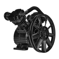
$(/,; Recommended pulley size is 3.75″.
To calculate needed pulley diameter, multiply
Pump Pulley Diameter (10.5″) by Pump RPM
(1300). Divide this number by motor RPM to get
the necessary motor pulley size. See Figure A.
I1E2+,)";))S5:F2:5/1(.)8(+)R(/(+)T2::,4
3. Pump Flywheel (31) must be in perfect alignment
with motor pulley. Misalignment between motor
and Pump can cause damage to equipment.
4. Verify that Pump Flywheel turns freely where
it overhangs the mounting surface.
5. Place a Type A Belt (not included) over Pump
Flywheel and motor pulley (not included).
6. Pull Compressor Pump until properly aligned,
and the belt is tight. Recheck alignment of
motor pulley, belt, and Pump Flywheel.
7. To mount Compressor Pump:
a. Use mounting holes in Compressor Pump
Base as a template to mark spots where four
holes will be drilled into mounting surface.
b. Move Compressor Pump aside, and drill four
5/16″ diameter holes in the mounting surface.
c. Move Compressor Pump back to mounting
position and secure each corner of the base
with a 5/16″ diameter Grade 5 (or better) bolt,
washer, lock washer, and nut (all not included).
d. Recheck Pump, belt, and pulley alignment.
Make adjustments as necessary.
$(/,; To test proper tension on belt, press down on belt.
There should be 1/2″ deflection or less at mid span.
8. Connect plumbing hardware (not included) from Air
Outlet to Air Destination (i.e., air pressure tank of
compressor, not included).Route tubing in shortest
possible path.
9. Depending on the air tool, you may need to incorporate
additional components, such as in-line oiler, filter, or
dryer (all sold separately), as shown in Figure C and
D on page 8 and 9. Consult your air tool’s manual for
needed accessories.
10. Install safety guard (not included) that surrounds motor
pulley, belt, and Pump Flywheel. Safety guard should
cover all sides of moving belt and pulleys. Safety guard
must have one inch clearance from all moving parts
and should be sturdy enough to prevent injury.
!5+.1.Ei Do not operate Air Compressor
Pump without safety guard in place.
11. Fill Compressor Pump Crankcase with appropriate
amount of Air Compressor Oil (sold separately).
S7,FY1.E)V1:)U,-,:
1. Check oil level before operating Air Compressor Pump.
%RTV#'"$'; Running Pump with no oil or low oil will
cause damage to equipment and void warranty.
2. Fill Pump Crankcase with synthetic non-
detergent Air Compressor Oil.
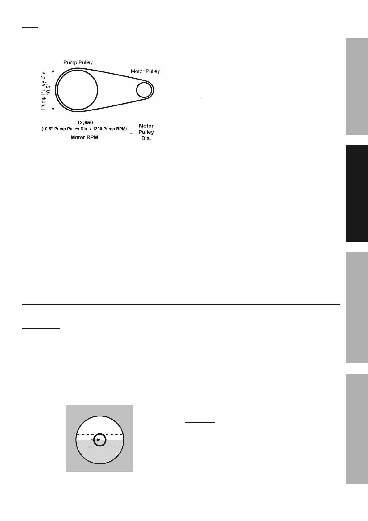
3. Oil level should be at the center of the FULL level
on the Oil Sight Glass (21). Add oil as needed to
maintain this level. Do not let oil level go below
center circle (LOW) and do not fill oil above center
circle (OVERFILL). See Figure B.
V@G#I%UU
UV!
I\UU
I1E2+,)W;)))V1:)P1E7/)&:500
4. To add oil:
a. Remove the Oil Fill Plug.
b. Using a funnel to avoid spills, pour enough
oil into the Pump Crankcase to reach
the “full” level in the Oil Sight Glass.
c. Replace the Oil Fill Plug.
5. If uncertain which oil to use for this compressor,
call Harbor Freight Tools customer service
at 1-888-866-5797 for assistance.
6. S75.E,)/7,)F(9*+,00(+)(1:)58/,+)/7,)81+0/)
7(2+)(8)20,)/()+,9(-,)5.4)6,B+10D
S"\'%V$i)'V)T#G@G$')%$f\#Q)I#VR)W\#$P;)
X().(/)566)(+)F75.E,)/7,)(1:)A71:,)
/7,)F(9*+,00(+)10)1.)(*,+5/1(.D))
"::(A)/7,)F(9*+,00(+)/()F((:)B,8(+,)+,*:5F1.E)(1:D
 Loading...