PHono: Connect a pair of cables from a record player with a moving magnet type phono
cartridge to the PH inputs.
14. GND (Ground)
If the phono player being used has a separate Ground lead, connect it to the GND
terminal.
15. CD1 and CD2 CONTROL
Connect Control cables from the C38 CD1 and CD2 CONTROL connectors to the mat-
ching connectors on a Mcintosh CD player and changer. This connection allows you to con-
trol the CD units from the HR38 or a WK-1 wall mounted Keypad.
Connect cables from the C38, CD1 or CD2 DATA PORTS to the Data Inputs on a CD
player and changer. These connections allow you to control the CD units with their own hand
held remote controllers transmitting directly to the C38 front panel or remote IR sensors.
16. TO MULTI-ROOM CONTROLLER
This 25 pin connector allows you to add a Mcintosh CR10 Remote Control System. The
CR10 can provide as many as four additional remote controlled listening areas, for a total
of six. Additional CR 10 units can also be cascaded for even more control areas. Each CR 10
adds the capability of four areas.
All program signal sources connected to the C38, except for Tape 3 and CD1, are available
for selection by a CR10.
17. TUNER CONTROL
Connect a control cable from the C38 TUNER CONTROL jack to the matching jack on
a Mcintosh tuner. This connection allows you to operate the tuner with the HR38 or WK-1
wall mounted Keypad.
18. SCR (Optional Speaker Control relay)
The Mcintosh SCR-3 SPEAKER CONTROL RELAY provides capability for switching two
pairs of speakers using the front panel SPEAKERS 1 and 2 pushbuttons. The SCR-3 also in-
cludes two high current AC outlets with a total current capacity of 1800 watts to operate ac-
cessory components such as large power amplifiers. These outlets turn on and off with the
C38 POWER switch and can be used when the accessory components demand more cur-
rent than the 1400 watt rating of the rear panel AC outlets controlled by the C 38 Power switch.
Plug the nine pin computer type connector from the SCR-3 into the SCR socket on the
C38 rear panel. Plug the heavy AC cable from the SCR-3 into a wall outlet.
DO NOT PLUG THE SCR-3 HEAVY AC CABLE INTO ANY OF THE C38 REAR PANEL AC
OUTLETS.
AC power control for additional accessories can be accommodated by adding the
optional Mcintosh R612 or PC-2 AC Power Controller.
19. EXTERNAL SENSORS, AREA A and AREA B
A coaxial connector is provided for a remote IR sensor to control Area A, in addition
to the built-in front panel sensor. The external sensor can be either the R649 wall mounted
sensor, or the WK-1 Keypad.
A coaxial connector is also provided for an IR sensor or keypad for remote control in Area B.
The wall mounted R649 IR sensor and the WK-1 keypad have a status indicator built in.
A red LED lights whenever the system is on and operating. The LED will blink on and off when
the area is muted.
12
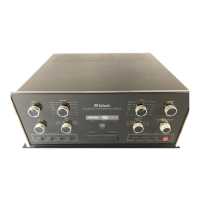
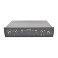
THE REAR PANEL
AND
HOW TO MAKE
CONNECTIONS
 Loading...