EasyManua.ls Logo

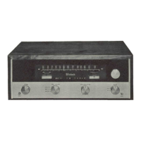
McIntosh MR 71

McIntosh MR 71
12 pages
To Next Page IconTo Next Page
To Previous Page IconTo Previous Page
Loading...
SCHEMATIC
NOTES
1.
R10l|
does
not
appear
in
unite
below
aerial
number
78B30.
2.
R29
had
a
different
value
in
earlier
units.
3.
C6
was
lOpP
in
earlier
units.
4.
R27
was
either
1.2K
ohms
or
2.2K
ohms
in
earlier
units.
3.
R103
does
not
appear
in
units
below
serial
number
67BOO.
6.
L6
was
not
used
in
some
units
below
serial
number
21B30;
LI
was
link
coupled
to
L2.
7.
G100
was
used
in
some
units
below
serial
number
66B33-
8
.
R
38
was
220K
ohms
in
earlier
units.
9.
C101
does
not
appear
in
some
earlier
units.
10.
In
all
units
below
serial
number
62B00,
C7
was
220pF
and
CI
4.3
was
.OlpF
(disc);
R102
was
not
used.
11.
In
all
units
below
serial
number
38B00,
R92
and
93
was
680
ohms,
Rl|3
was
6.8K,
and
R
6
I
4
.
was
220K.
12.
R
96
was
10
ohms
in
all
units
below
serial
number
39BOO.
13.
C58
was
a
.OlpF
(2
section)
capacitor
in
earlier
units.
llj..
R99
does
not
appear
in
earlier
units.
l3.
C99
and
R100
do
not
appear
in
units
below
serial
number
43B00.
Refer
to
McIntosh
Service
Bulletin
#114
(part
number
038-141)
16.
C33
was
lOpF
in
all
units
below
serial
number
43B00.
17.
R3
was
3K
ohms
in
some
earlier
units.
18.
In
all
units
below
serial
number
86
B
6
O,
C71
is
.0027
5%
100V.
(Part
No.
063-004)

Other manuals for McIntosh MR 71

Related product manuals