7
Installation
Installation
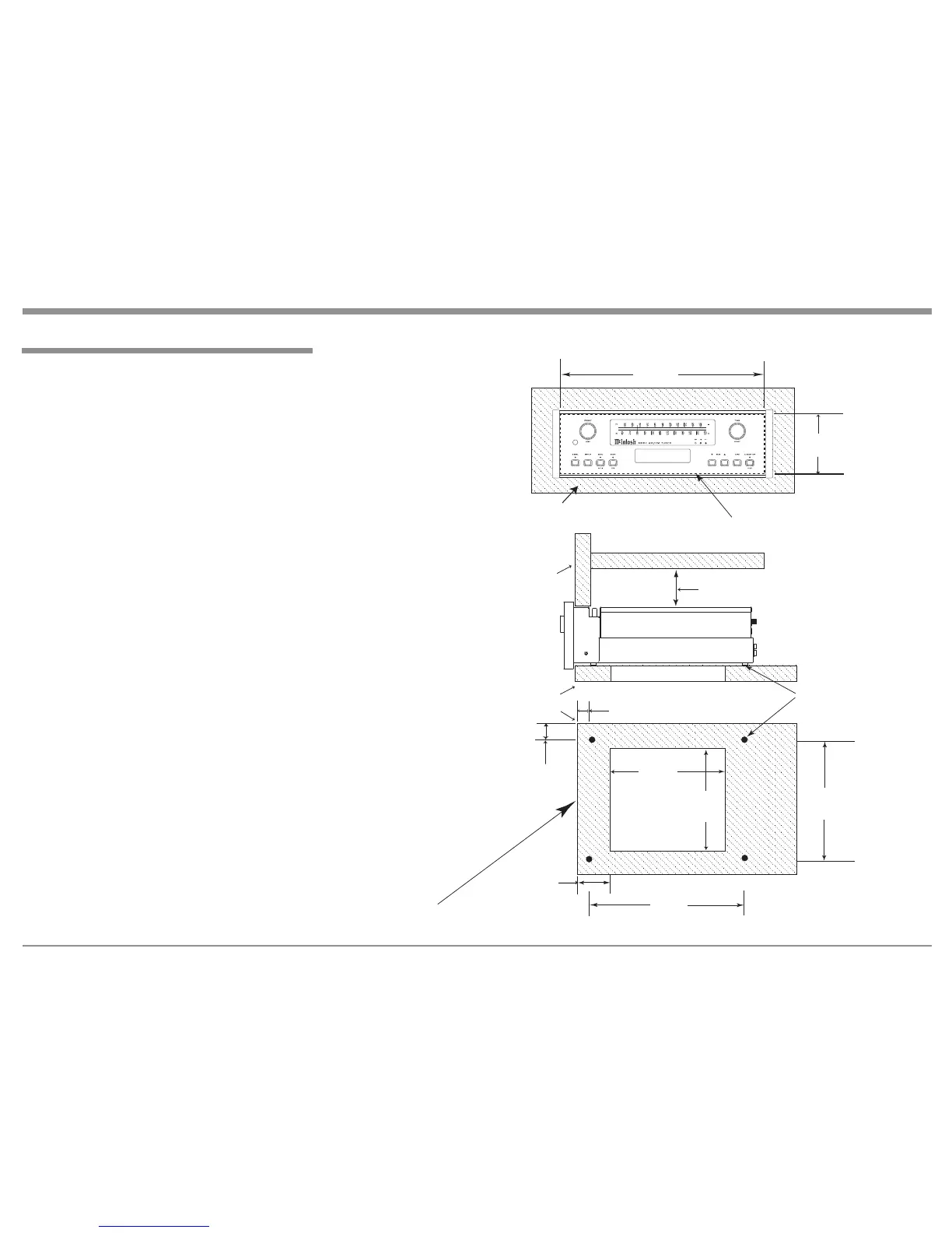
The MR87 can be placed upright on a table or shelf,
standing on its four feet. It also can be custom in-
stalled in a piece of furniture or cabinet of your
choice. The four feet may be removed from the bottom
of the MR87 when it is custom installed as outlined
below. The four feet together with the mounting
screws should be retained for possible future use if the
MR87 is removed from the custom installation and
used free standing. The required panel cutout, ventila-
tion cutout and unit dimensions are shown.
Always provide adequate ventilation for your
MR87. Cool operation ensures the longest possible
operating life for any electronic instrument. Do not
install the MR87 directly above a heat generating
component such as a high powered amplifier. If all
the components are installed in a single cabinet, a
quiet running ventilation fan can be a definite asset in
maintaining all the system components at the coolest
possible operating temperature.
When the MR87 is placed free-standing on a flat
surface, allow at least 2 inches (5.08cm) above the
top, 2 inches (5.08cm) below the bottom and 2 inches
(5.08cm) on each side of the Tuner, so airflow is not
obstructed. Allow 19-1/2 inches (49.53cm) depth
behind the front panel. Allow 1-7/16 inch (3.66cm) in
front of the mounting panel for knob clearance.
A custom cabinet installation should provide the
minimum spacing dimensions for cool operation. Al-
low at least 2 inches (5.08cm) above the top, 2 inches
(5.08cm) below the bottom and 2 inches (5.08cm) on
each side of the Tuner, so airflow is not obstructed.
The Custom Cabinet should be open backed and at
least 12 inches (30.48cm) away from any surface such
as a wall. Be sure to cut out a ventilation hole in the
mounting shelf according to the dimensions in the
drawing. Allow 1-7/16 inch (3.66cm) in front of the
mounting panel for knob clearance.
 Loading...