5
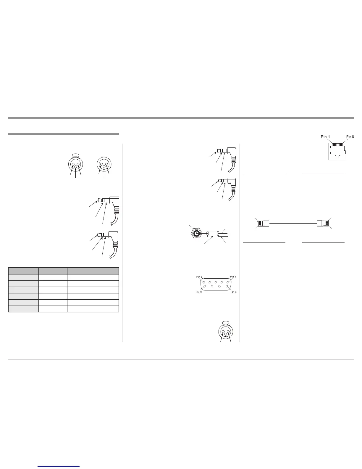
Ethernet RJ45 Socket
1. Tranceive Data (+) 5. N/C
2. Tranceive Data (-) 6. Receive Data (-)
3. Receive Data (+) 7. N/C
4. N/C 8. N/C
Ethernet Cable - Straight Thru Connections
Pin Number - Wire Color Pin Number - Wire Color
1. Orange/White → 1. Orange/White
2. Orange → 2. Orange
3. Green/White → 3. Green/White
4. Blue → 4. Blue
5. Blue/White → 5. Blue/White
6. Green → 6. Green
7. Brown/White → 7. Brown/White
8. Brown → 8. Brown
Ethernet Cable - Crossover Connections
Pin Number - Wire Color Pin Number - Wire Color
1. Orange/White → 1. Green/White
2. Orange → 2. Green
3. Green/White → 3. Orange/White
4. Blue → 4. Blue
5. Blue/White → 5. Blue/White
6. Green → 6. Orange
7. Brown/White → 7. Brown/White
8. Brown → 8. Brown
Data Output and IR IN Port Connectors
The MX151 Data Out Ports send Remote Control Sig-
nals to McIntosh Source Compo-
nents. A 1/8 inch stereo mini phone
plug is used for connection.
The IR IN Port also uses a 1/8
inch stereo mini phone plug and al-
lows the connection of other brand
IR Receivers to the MX151.
Zone A and B Sensor Connectors
The MX151 Zone A and B Sensor Connectors receive
Control Signal Data from a McIntosh IR Sensor and
also provides +5VDC
for the Sensor Circuitry.
Connections between the
MX151 and the Sensor is
made using a RG59U or
RG6 Coax Cable (300ft
max.) with “F” Connectors at both ends.
RS232 DB9 Connector Pin Layout
1. N/C 6. N/C
2. Data Out (TXD) 7. N/C
3. Data In (RXD) 8. N/C
4. N/C 9. N/C
5. Gnd.
Microphone XLR Connectors
Below is the Pin configuration for the Mi-
crophone Connector on the MX151. Refer to
the diagram for connections:
PIN 1: Shield/Ground
PIN 2: Signal
PIN 3: +8.9VDC
XLR Connectors
Below is the Pin configuration for the XLR Balanced
Output Connectors on the MX151. Refer to the dia-
grams for connections:
PIN 1: Shield/Ground
PIN 2: + Signal
PIN 3: - Signal
PC (Power Control) and Trigger Connectors
The MX151 Power Control Out and Trigger Output
Jacks send Power On/Off Sig-
nals when connected to other
Components. An additional
connection on the Main Power
Control Jack is for controlling
the illumination of the Power
Output Meters on McIntosh
Power Amplifiers. A 1/8 inch
stereo mini phone plug is used
for connection to the Power
Control and Trigger Outputs on
the MX151.
Jack Label Voltage Meter Illumination Control
ZA PC Out 5 Volts Yes
ZB PC Out 5 Volts Yes
Trigger Out 1 5 Volts Yes
Trigger Out 2 5 Volts Yes
Trigger Out 3 5 or 12 Volts
1
Yes
Trigger Out 4 5 or 12 Volts
1
Yes
Connector and Cable Information