OS-10V 02/04/2001 Rev.2
11
For rise time and fall time measurements, the 10% and 90% amplitude points are used as
starting and ending reference points.
(1) Apply a signal to the input jack [18].
(2) Use the VOLTS/DIV and VAR controls to adjust the waveform peak to peak height to
five divisions.
(3) Adjust vertical position so that the tops of the waveform coincide with 100% point,
while the bottoms of the waveform coincide with 0% point.
(4) Adjust Sweep switch to obtain the positive-going direction or negative-going
direction of the waveform on the screen.
(5) Use the horizontal POSITION control to adjust the 10% points to coincide with a
vertical reference line.
(6) Measure the horizontal distance in divisions between the 10% and 90% points on the
waveform (divisions).
(7) Pulse rise time and fall time measurement is calculated by the following equation:
Horizontal distance (div) × sensitivity (Time/div)
Rise Time = -----------------------------------------------------------
Horizontal factor
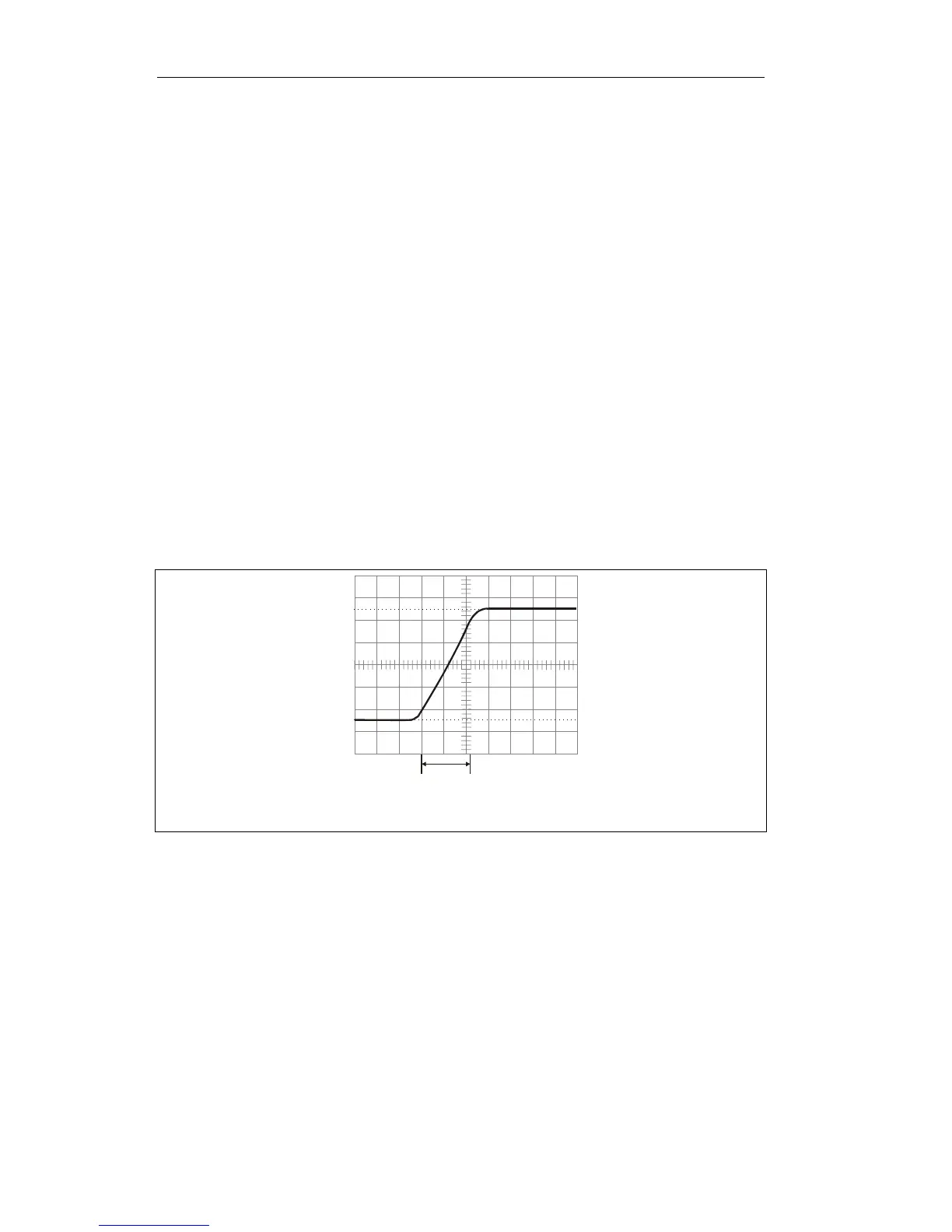
For the example shown in Fig.4-7, the horizontal distance from 10% to 90% is 2.4
divisions, the sweep TIME/DIV setting is 1µS/DIV, factor x 1. The rise time is
calculated as follows:
1µS/DIV × 2.4DIV
Rise Time = ------------------------------ = 2.4µS
1
Fig. 4-7
4.4 TV Signals measurement
Steps :
(1) Connect TV signals to INPUT jack [19]
(2) Set Trigger method to “TV” [10], Sweep switch turn to 2mS/Div.
(3) Observe the screen, it should be negative synchronize pulse wave.
(4) Adjust VOLTS/DIV and VAR to obtain proper range.
4.5 X– Y mode applications
10%
90%
100%
2.4DIN
 Loading...