- 16 -
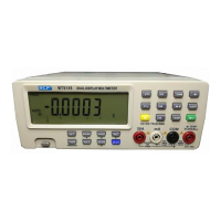
5.13 Real-time Graph Window
Before applying this function, user must choose a desired measuring range. The X axis indicates system time,
while the Y axis indicates the range of testing data.
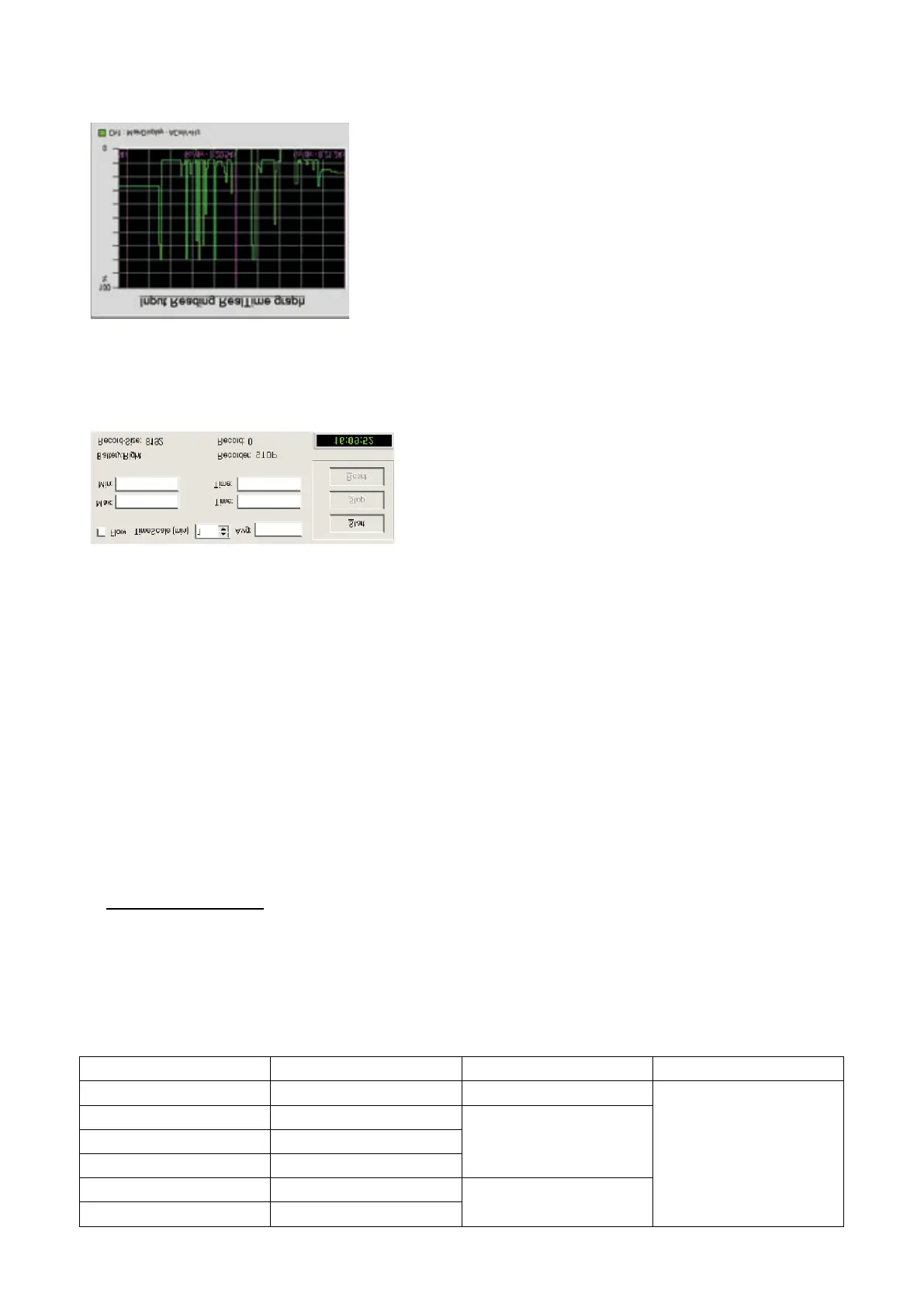
5.14 Recorder Control Panel
In this panel function, user can set up the recording time, max.and min. values. The Start, Stop and Reset buttons
are used to control the data recorder. Click Start button to start the data recording and Stop button to stop the data
recording. In the meanwhile, the data has been stored in the History.txt file.
Click the Reset button to clear the current data in History.txt file, and get ready for the next data recording.
Recorder, Record time and Record in the bottom part of the panel indicate the current status of the data recorder.
Battery indicates the power supply status of the multimeter. If power supply is in good status, it will display
“Battery: High”. Otherwise, it will display “Battery: Low”.
In the right corner of the bottom displays the system time.
Should you have any questions regarding this software or any suggestions to us, please write down and inform us.
We will do the utmost to improve the software.
6. SPECIFICATIONS
6.1 Electrical Specifications
The accuracy is specified for one year after calibration at operating temperature of 18℃ to 28℃, with humidity at
0%~75%.
Accuracy specifications take the form of: ± (a% of reading+number of least significant digits).
Table1. DCV
Range Resolution Accuracy Remarks
80mV 1μV ±(3% rdg+10)
Input impedance:
80mV~800mV: >1000MΩ
8V~1000V: 10MΩ
800mV 10μV
±(0.05% rdg+5) 8V 0.1mV
80V 1mV
800V 10mV
±(0.08% rdg+10)
1000V 0.1V
 Loading...