56 AGZ 026B through 130B IOMM AGZ-5
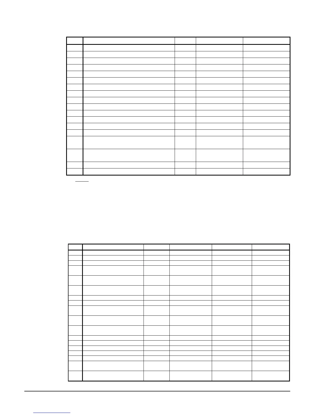
Table 37, Digital Inputs
# Description Type Signal Signal
1 Unit OFF Switch UT 0 VAC (Disable) 24 VAC (Enable)
2 Pump Down Switch #1 C1 0 VAC (Disable) 24 VAC (Enable)
3 Evaporator Water Flow Switch UT 0 VAC (No Flow) 24 VAC (Flow)
4 Open
5 Open
6 Pump Down Switch #2 C2 0 VAC (Disable) 24 VAC (Enable)
7 Open
8 Open
9 Phase Voltage Fault #1 (See Note 1) C1 0 VAC (Fault) 24 VAC (No Fault)
10 Phase Voltage Fault #2 (See Note 1) C2 0 VAC (Fault) 24 VAC (No Fault)
11 Ground Fault Prot. #1 (See Note 2 Below) C1 0 VAC (Fault) 24 VAC (No Fault)
12 Ground Fault Prot. #2 (See Note 2 Below) C2 0 VAC (Fault) 24 VAC (No Fault)
13 Remote Start/Stop UT 0 VAC (Disable) 24 VAC (Enable)
14 Open
15 Mechanical High Pressure/Motor Protect
Circuit 1
C2 0 VAC (Fault) 24 VAC (No Fault)
16 Mechanical High Pressure/Motor Protect
Circuit 2
C2 0 VAC (Fault) 24 VAC (No Fault)
17 Ice Mode Switch UT 0 VAC (Cool) 24 VAC (Ice)
18 Open
NOTES:
1. See Safety Alarms Table for “Phase Voltage Protection”. Units with single point electrical connection
will have one PVM with Inputs 9 and 10 wired together. Units with multiple point connection will
have two PVM’s with Input 9 for Electrical Circuit #1 and Input 10 for Electrical Circuit #2.
2. See Safety Alarms Table 40 for “Ground Fault Protection”. Units with single point electrical
connection will have one GFP with Inputs 11 and 12 wired together. Units with multiple point
connection will have two GFP’s with Input 11 for Electrical Circuit #1 and Input 12 for Electrical
Circuit #2.
Table 38, Digital Outputs
No. Description Type Load Output OFF Output ON
1 Alarm C1,C2,UT Alarm Indicator Alarm OFF Alarm ON
2 Evaporator Water Pump UT Pump Contactor Pump OFF Pump ON
3 Condenser Fan #1 C1 Fan Contactor Fan OFF Fan ON
4
Motor Control Relay #1 =
Compr#1
C1 Starter Compressor OFF Compressor ON
5
Motor Control Relay #3 =
Compr#3
C1 Starter Compressor OFF Compressor ON
6
Motor Control Relay #5 =
Compr#5
C1 Starter Compressor OFF Compressor ON
7 Liquid Line #1 C1 Solenoid Cooling OFF Cooling ON
8 Condenser Fan #2 C2 Fan Contactor Fan OFF Fan ON
9
Motor Control Relay #2 =
Compr#2
C2 Starter Compressor OFF Compressor ON
10
Motor Control Relay #4 =
Compr#4
C2 Starter Compressor OFF Compressor ON
11
Motor Control Relay #6 =
Compr#6
C2 Starter Compressor OFF Compressor ON
12 Liquid Line #2 C2 Solenoid Cooling OFF Cooling ON
13 Condenser Fan #3 C1 Fan Contactor Fan OFF Fan ON
14 Hot Gas Bypass #1 C1 Solenoid Cooling OFF Cooling ON
15 Hot Gas Bypass #2 C2 Solenoid Cooling OFF Cooling ON
16 Condenser Fan #4 C2 Fan Contactor Fan OFF Fan ON
17
Condenser Fan #5 ( on 8
Fans Only)
C1 Fan Contactor Fan OFF Fan ON
18
Condenser Fan #6 ( on 8
Fans Only)
C2 Fan Contactor Fan OFF Fan ON
 Loading...

