70 AGZ 026B through 130B IOMM AGZ-5
NOTE: The inverter 7-segment display shows lower case “b” and “d,” meaning the same as the
upper case letters “B” and “D” used in this manual (for uniformity “A to F”).
NOTE: The Store Key saves the edited parameter (shown in the display) to the EEPROM in the
inverter, regardless of the programming device. Upload and download of parameters is
accomplished through a separate command—do not confuse Store with Download or Upload.
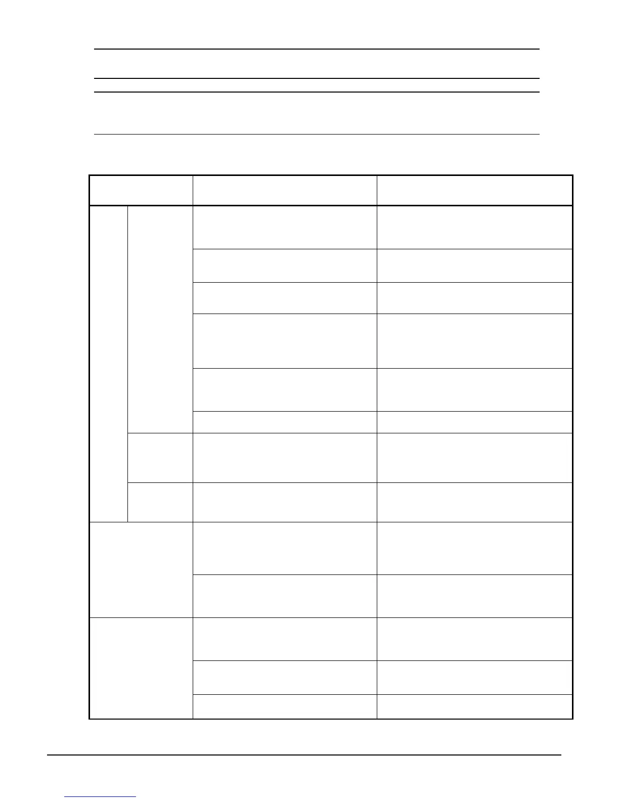
Troubleshooting Tips
The table below lists typical symptoms and the corresponding solution(s).
Symptom
Condition
Probable Cause Solution
• Is the frequency command source A_01
parameter setting correct?
• Is the Run command source A-02
parameter setting correct?
• Make sure the parameter setting A-01 is
correct.
• Make sure the parameter setting A-02 is
correct.
• Is power being supplied to terminals [L1],
[L2], and [L3/N]? If so, the POWER lamp
should be ON.
• Check terminals [L1], [L2], and [L3/N], then
[U/T1], [V/T2], and [W/T3].
• Turn ON the power supply or check fuses.
• Is there an error code E X X displayed? • Press the Func. key and determine the error
type. Eliminate the error cause, then clear the
error (Reset).
• Are the signals to the intelligent input
terminals correct?
• Is the Run Command active?
Is the {FW] terminal (or [RV]) connected to
[P24] (via switch, etc.)
• Verify the terminal functions for C_01 – C_05
are correct.
• Turn ON Run Command enable.
• Supply 24V to {FW] or [RV] terminal, if
configured.
• Has the frequency setting for F_01 been
set greater than zero?
• Are the control circuit terminals [H], [O],
and [L] connected to the potentiometer?
• Set the parameter for F_01 to a safe, non-
zero value.
• If the potentiometer is the frequency setting
source, verify voltage at [O] > 0V.
The inverter
outputs [U],
[V], [W] are
not supplying
voltage.
• Is the RS (reset) function or FRS (free-run
stop) function ON?
• Turn OFF the command(s).
Inverter
outputs [U],
[V], [W] are
supplying
voltage.
• Is the motor load too heavy? • Reduce load, and test the motor
independently.
The
motor
will not
run.
The optional
remote
operator is
used (SRW).
• Are the operational settings between the
remote operator and the inverter unit
correct?
• Check the operator type setting.
• Are the connections of output terminals
[U/T1], [V/T2], and [W/T3] correct?
• Is the phase sequence of the motor
forward or reverse with respect to [U/T1],
[V/T2], and [W/T3]?
• Make connections according to the phase
sequence of the motor. In general:
FWD = U-V-W, and
REV = U-W-V.
The direction of the motor
is reversed.
• Are the control terminals [FW] and [RW]
wired correctly?
• Is parameter F_04 properly set?
• Use terminal [FW] for forward, and [RV] for
reverse.
• Set motor direction in F_04.
• If using the analog input, is the current or
voltage at [O] or [OI]?
• Reduce the load.
• Heavy loads activate the overload restriction
feature (reduces output as needed).
• Is the load too heavy? • Reduce the load
• Heavy loads activate the overload restriction
feature (reduces output as needed).
The motor speed will not
reach the target
frequency (desired
speed).
• Is the inverter internally limiting the output
frequency?
• Check max frequency setting (A_04).
• Check frequency upper limit setting (A_61).
Continued on next page.
 Loading...

