82 AGZ 026B through 130B IOMM AGZ-5
VIEW UNIT STATUS (5)
D.I. 111111111
123456789012345678
111111111111111111
This menu gives the status of digital inputs (D.I.). 1=ON, 0=OFF. Numbers are 1
through 18. See Table 37, Digital Inputs, on page 56 for number reference.
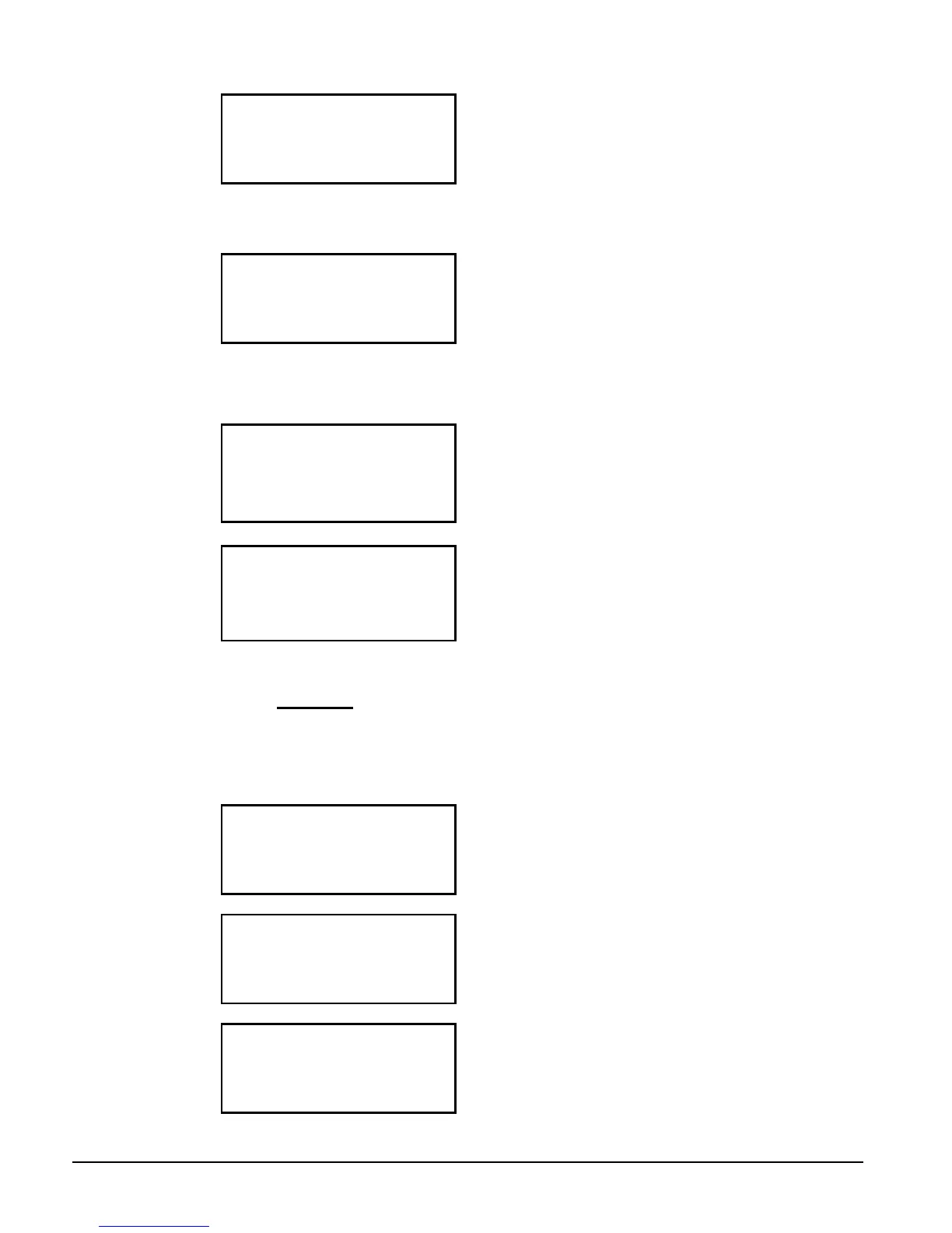
VIEW UNIT STATUS (6)
Analog Outputs
(volts X 100)
1=XXX.X 2=XXX.X
This menu give the output voltage for fans #1 and #2 VFD. Divide by 100 for actual
voltage.
VIEW UNIT TEMPERATURES
VIEW UNIT TEMP (1)
Evap LWT = XXX.X °
°°
°F
OAT = XXX.X °
°°
°F
LWT Target = XX.X °
°°
°F
VIEW UNIT TEMP (2)
LWT Pulldn=XX.X °
°°
°F/m
Control Band=XX.X °
°°
°F
VIEW CIRCUIT STATUS
The following four screens are duplicated for circuit # 2. Units with two
compressors per circuit (AGZ 026 through AGZ 090) will not have screen #4
present. Circuit 1 has compressor #1, #3, (#5), circuit 2 has compressor #2, #4,
(#6).
VIEW CIR1 STATUS (1)
Off:Pumpdown Switch
VIEW CIR1 STATUS (2)
Comp1=Off
Hours= XXXXX
Starts= XXXXX
VIEW CIR1 STATUS (3)
Comp3=Off
Hours= XXXXX
Starts= XXXXX
 Loading...

