IM 1017/Page 61 © 2009 McQuay International 800-432-1342 www.mcquay.com
Table 3: Dip Switch Configuration
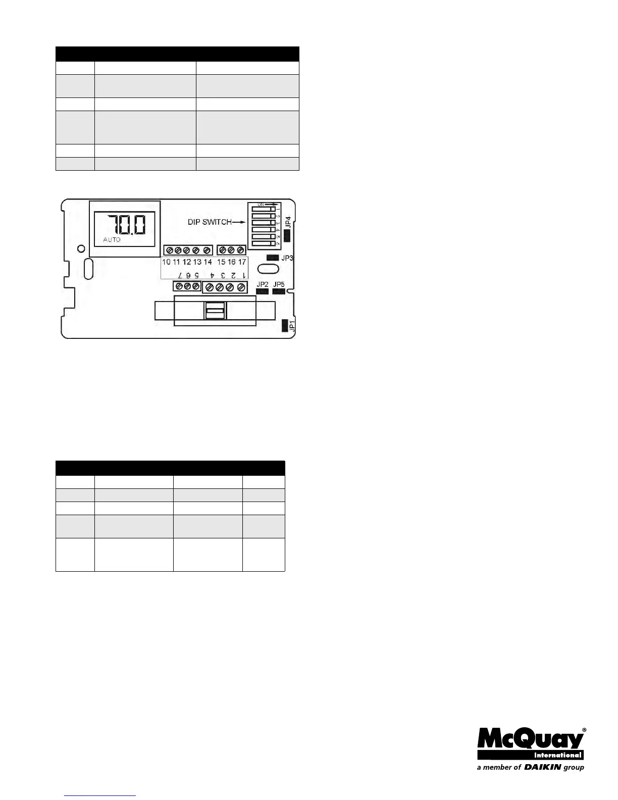
Note: * On is with the dip switch handle to the right. See diagram below.
Figure 3: Circuit Board
Service Menu:
Access: Press UP and DOWN arrows for 5 seconds.
Menu Selection: Select 1 to 5 by pressing the mode button or
by pressing the UP and DOWN arrows simultaneously.
Adjust Value: Use UP or DOWN arrow.
Table 4: Service Functions
Switch Closed On* Open Off
1 Not Used Not Used
2
Staged Heat
3°F Diff. (Term. 13)
Aux. Heat No Diff.
(Term. 13)
3 F Display C Display
4
Main & Sec. Outputs
0-10 VOC (Term. 10 & 11)
requires JP4 & JP5
Main & Sec. Outputs
4-20 mA (Term. 10 & 11)
Remove JP4 & JP5
5 Operating Position Not Used
6 Setback= 90°F & 50°F Setback = 85°F & 60°F
Item # Function Range Default
1 Zone Temp Offset -5.1 F to 5.1 F 0 F
2 Valve Stroke Time 30 sec. to 5 min. 120 sec.
3 Fan Delay to OFF 2 to 10 minutes 120 sec.
4
Compressor
Minimum Off Time
30 seconds to 10
minutes
120 sec.
5Purge Cycle
0 = time based
1 = temperature
based
1