Do you have a question about the McQuay FCVS and is the answer not in the manual?
Essential safety precautions, warnings, and code compliance for installation.
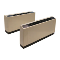
Procedures for securely mounting the fan coil unit to a wall or suitable surface.
Guidelines and procedures for connecting water piping to the unit.
Procedures for making field electrical power connections to the unit.
Steps to follow before the unit's first operation, including system flushing.
Detailed steps for cleaning and flushing the hydronic system before startup.
Overview of available control options and their operation.
Description and function of the LV interface board for unit control.
Routine maintenance tasks and performance recording recommendations.
Guidance on when and how to change the unit filters.
Instructions for checking and cleaning condensate drain pans.
Step-by-step guide to remove the drain pan and motor for access.
Wiring diagram for a typical fan coil with a solid-state thermostat.
Wiring diagram for fan coil with unit-mounted 3-speed fan switch.
Wiring diagram for fan coil with electric heat and LV interface board.
Instructions for installing normally closed valve packages.
Steps for providing power to the thermostat from the interface board.
Instructions for installing the MT 168 thermostat.
Explains mode button, fan speed, and up/down arrow operations for MT 168.
Steps for mounting and wiring the T170 thermostat.
Provides instructions for mounting and wiring the T170 thermostat.
Steps to check T170 thermostat functionality after installation.
Details the nine functions accessible via the T170 thermostat menu.
Explains standard and staged fan configurations for the T170 thermostat.
Safety precautions for installing the automatic changeover switch.
Steps for installing the automatic changeover switch.