McQuay IM 1089 Page 49
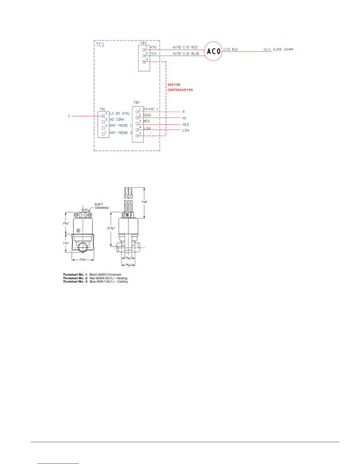
Figure 4: Thermostat TB155 autochangeover to be used with On-Off 24V valve packages, SPDT ACO and unit-mounted
Low Voltage Interface Board
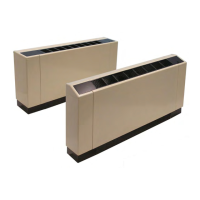
Figure 5: Automatic changeover switch
(SPDT ACO Kit P/N 039398600)
• Connect a wire from thermostat terminal TB2- 24
( Low fan speed) to the Low terminal
• Remove Jumper JP1 to allow the remote mounted
10K Return Air Sensor to operate.
• Mount the 10K Return Air Sensor (PN 107345501) above the
filter through the knockout provided
Note: (1) If a fan coil unit is to be used for heating or cooling
only, the SPDT ACO Switch (SPDT ACO Kit P/N
039398600) is not required. For such applications just
follow Step 2.
Four-pipe system (Cooling and Heating)
Two piping packages will be required for CW and HW coils.
The following accessories needed for field-installed thermostat
model T*155 (unit-mounted or wall-mounted):
• Thermostat TA155 (kit) – PN 107345302 or Thermostat
TB155 (kit) – PN 107345304
• 10K Return Air Sensor - PN 107345501 for unit-mounted
applications only (for wall-mounted applications the sen-
sor is imbedded with the thermostat)
Step 1: Installing valve packages
• Solder the appropriate inlet and outlet CW pipe connections
from the valve package to the coil connections.
• Solder the appropriate inlet and outlet HW pipe connections
from the valve package to the coil connections.
• Snap-on the Quick-connects of the valve actuators to the
appropriate terminals of the Low Voltage Interface Board as
per Fig. 2.
Step 2: Provide power to thermostat
(refer to Fig. 2 and 4)
• Connect a wire from thermostat terminal TB1- 4 (L2 Neutral)
to the common terminal on the interface board (terminal C)
• Connect a wire from thermostat terminal TB2- 1 (24VAC) to
the 24 V terminal connection R.
• Connect fan speed wires from the thermostat to the
appropriate Low Voltage Interface Board terminals:
• Connect a wire from thermostat terminal TB2- 2 ( High
fan speed) to the HI terminal
• Connect a wire from thermostat terminal TB2- 3 ( Med
fan speed) to the Med terminal
• Connect a wire from thermostat terminal TB2- 24 ( Low
fan speed) to the Low terminal
• Remove Jumper JP1 to allow the remote mounted the
10K Return Air Sensor to operate.
• Mount the 10K Return Air Sensor (PN 107345501) above the
filter through the knockout provided
Note: (2) For thermostats supplied by others refer to the
manufacturer’s installation literature and use this manual
as a guideline only.