Page 57 © 2010 McQuay International 800-432-1342 www.mcquay.com
Application Notes
1 When no pipe sensor is used the main output controls
cooling and the secondary output controls heating.
2 The pipe sensor should be mounted on the main coil
input for water system operation and in the main duct
system for forced air operation.
3 The set point and operating mode will be retained on a
loss of power.
4 When using either a remote probe or pipe sensor, run
wiring away from any electrical motors or power wiring.
Service Menu
Access: Press UP and DOWN arrows for 5 seconds.
Menu Selection: Select 1 to 5 by pressing the mode button or
by pressing the UP and DOWN arrows simultaneously.
Adjust Value: Use UP or DOWN arrow.
Table 3: Service Menu Functions
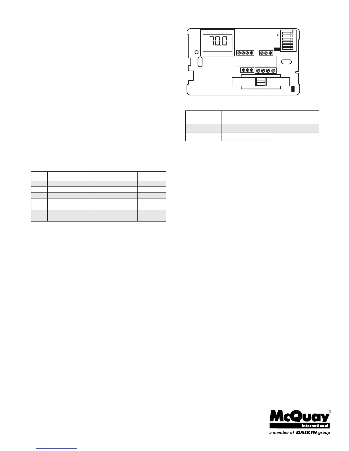
Figure 3: Circuit Board Jumpers
Table 4: Circuit Board Jumper Configuration
Power-Up Operating Sequence
Upon application of power, an MTA158 will go directly to
normal operation.
Item # Function Range Default
1 Zone Temp Offset -5.1 F to 5.1 F 0F
2 Valve Stroke Time 30 sec. To 5 min. 120 sec.
3 Fan Delay to OFF 0 to 10 Minutes 0 Sec.
4
Compressor
Minimum Off Time
30 Sec. To 10 min. 120 Sec.
5 Purge Cycle
0 = Time Based
1 = Temperature Based
1
Jumper
Designation
Jumper Installed
ON
Jumper
Removed
JP1 Local Sensing Remote Sensing
JP4 2 Pipe System* 4 Pipe System
AUTO
JP4
JP1
1
23
4 56
DIP SWITCH
ON
1 2 3 4 5 6 7
10 11 12 13
15 16 17