IM 1015/Page 53 © 2009 McQuay International 800-432-1342 www.mcquay.com
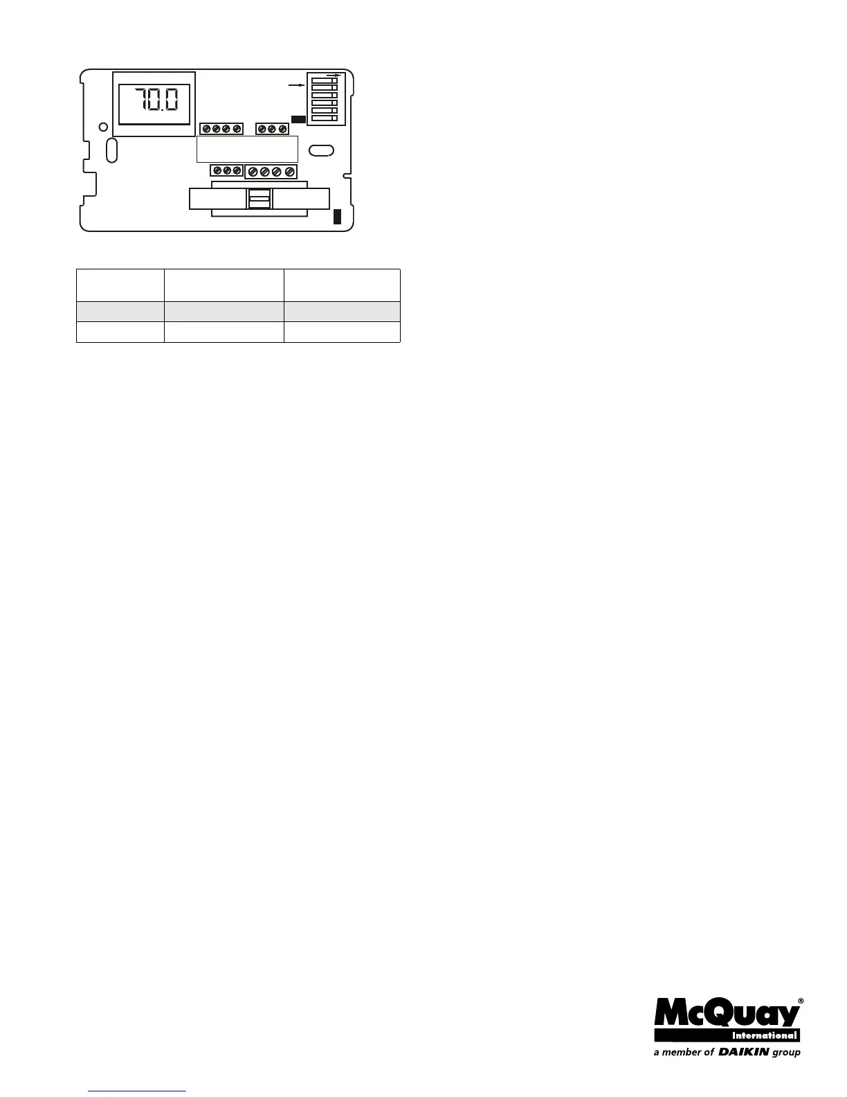
Figure 3: Circuit Board Jumpers
Table 3: Circuit Board Jumper Configuration
Application Notes
1 When no pipe sensor is used the main output controls
cooling and the secondary output controls heating.
2 The pipe sensor should be mounted on the main coil
input for water system operation and in the main duct
system for forced air operation.
3 The set point and operating mode will be retained on a
loss of power.
4 When using either a remote probe or pipe sensor, run
wiring away from any electrical motors or power wiring.
Power-Up Operating Sequence
Upon application of power, an MTA158 will go directly to
normal operation.
Jumper
Designation
Jumper Installed
ON
Jumper
Removed
JP1 Local Sensing Remote Sensing
JP4 2 Pipe System* 4 Pipe System
AUTO
JP4
JP1
1
23
4 56
DIP SWITCH
ON
1 2 3 4 5 6 7
10 11 12 13
15 16 17