P
Pedro MillerAug 8, 2025
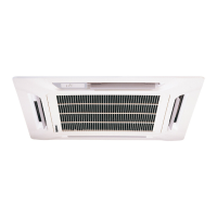
How to increase air flow in my McQuay MCK050A?
- HheathercookAug 8, 2025
If the airflow from your McQuay Air Conditioner is too low, try the following: 1. Clean the air filter. 2. Close any open doors and windows. 3. Clear any blockages from the air suction and discharge areas. 4. Increase the temperature setting.