EasyManua.ls Logo

McQuay MCK 020A

McQuay MCK 020A
101 pages
To Next Page IconTo Next Page
Loading...
MCK - 2004
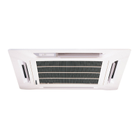
Ceiling Cassette Split Systems
Models: MCK 020A/AR
MCK 025A/AR
MCK 030A/AR
MCK 040A/AR
MCK 050A/AR
MCK 015B/BR
MCK 020B/BR
MCK 025B/BR
MCK 030B/BR
MCK 010C/CR
MCK 015C/CR
MCK 020C/CR

Questions and Answers:

McQuay MCK 020A Specifications

General IconGeneral
BrandMcQuay
ModelMCK 020A
CategoryAir Conditioner
LanguageEnglish

Summary

Special Features

Ultra Slim New Stylish Design Profile

Describes the slim design profile of the unit.

Turbo Mixed Flow Fan

Describes the efficient turbo fan for air circulation.

Built-In High Head Drain Pump

Features a built-in drain pump with a specific drain head.

Strong and Robust

Highlights the unit's durable casing and robust parts.

Friendly Serviceability

Details easy access for inspection and replacement of parts.

Microcomputer Remote Controller

Describes the features of the remote controller.

Wireless Remote Controller

Mentions the convenience of operating anywhere in the room.

CEILING CASSETTE A SERIES (COOLING ONLY) Specifications

CEILING CASSETTE A SERIES (HEAT PUMP) Specifications

CEILING CASSETTE A SERIES (COOLING ONLY - R407 C) Specifications

CEILING CASSETTE A SERIES (HEAT PUMP - R407 C) Specifications

CEILING CASSETTE B SERIES (COOLING ONLY) Specifications

CEILING CASSETTE B SERIES (HEAT PUMP) Specifications

CEILING CASSETTE B SERIES (COOLING ONLY - R407 C) Specifications

CEILING CASSETTE B SERIES (HEAT PUMP - R407 C) Specifications

CEILING CASSETTE C SERIES (COOLING ONLY) Specifications

CEILING CASSETTE C SERIES (HEAT PUMP) Specifications

Noise Level

MCK - AAR

Noise level data for MCK A/AR series models.

MCK - BBR

Noise level data for MCK B/BR series models.

MCK - CCR

Noise level data for MCK C/CR series models.

Operating Range

Cooling only

Defines the operating temperature range for cooling mode.

Heat pump

Defines the operating temperature range for heat pump mode.

Refrigerant Circuit

MCK015 B - MLC M4 LC015 B...

Refrigerant circuit diagram for specific MCK/MLC model series.

MCK025 A - MLC M4 LC025 B...

Refrigerant circuit diagram for specific MCK/MLC model series.

Performance Table: MCK020 A MLC020 B

Performance Table: MCK025 A MLC025 B

Performance Table: MCK030 A MLC030 C

Performance Table: MCK030 A MLC030 B

Performance Table: MCK040 A MLC040 C

Performance Table: MCK050 A MLC050 C

A Series (Cooling Only - R407 C) Performance Table

Model: MCK020 A M4 LC020 B

Performance data table for MCK020A / M4LC020B models (R407C).

Model: MCK025 A M4 LC025 B

Performance data table for MCK025A / M4LC025B models (R407C).

Model: MCK030 A M4 LC030 C

Performance data table for MCK030A / M4LC030C models (R407C).

Performance Table: MCK030 A M4 LC030 B

Performance Table: MCK040 A M4 LC040 C

Performance Table: MCK050 A M4 LC050 C

B Series (Cooling Only - R22) Performance Table

Model: MCK015 B MLC015 B

Performance data table for MCK015B / MLC015B models (R22).

Model: MCK020 B MLC020 B

Performance data table for MCK020B / MLC020B models (R22).

Model: MCK025 B MLC025 B

Performance data table for MCK025B / MLC025B models (R22).

Performance Table: MCK030 B MLC030 B

B Series (Cooling Only - R407 C) Performance Table

Model: MCK015 B M4 LC015 B

Performance data table for MCK015B / M4LC015B models (R407C).

Model: MCK020 B M4 LC020 B

Performance data table for MCK020B / M4LC020B models (R407C).

Model: MCK025 B M4 LC025 B

Performance data table for MCK025B / M4LC025B models (R407C).

A Series (Heating Only - R22) Performance Table

Model: MCK020 AR MLC020 BR (HEATING MODE)

Heating performance data for MCK020AR / MLC020BR.

Model: MCK025 AR MLC025 BR (HEATING MODE)

Heating performance data for MCK025AR / MLC025BR.

Model: MCK030 AR MLC030 CR (HEATING MODE)

Heating performance data for MCK030AR / MLC030CR.

Performance Table: MCK040 AR MLC040 CR (HEATING MODE)

Performance Table: MCK050 AR MLC050 CR (HEATING MODE)

A Series (Heating Mode -R407 C) Performance Table

Model: MCK020 AR M4 LC020 BR (HEATING MODE)

Heating performance data for MCK020AR/ M4LC020BR (R407C).

Model: MCK025 AR M4 LC025 BR (HEATING MODE)

Heating performance data for MCK025AR/ M4LC025BR (R407C).

Model: MCK030 ARM4 LC030 CR (HEATING MODE)

Heating performance data for MCK030AR/M4LC030CR (R407C).

Performance Table: MCK040 AR M4 LC040 CR (HEATING MODE)

Performance Table: MCK050 AR M4 LC050 CR (HEATING MODE)

B Series (Heating Mode - R22) Performance Table

Model: MCK015 BR MLC015 BR (HEATING MODE)

Heating performance data for MCK015BR/ MLC015BR (R22).

Model: MCK020 BR MLC020 BR (HEATING MODE)

Heating performance data for MCK020BR/ MLC020BR (R22).

Model: MCK025 BR MLC025 BR (HEATING MODE)

Heating performance data for MCK025BR/ MLC025BR (R22).

Performance Table: MCK030 BR MLC030 BR (HEATING MODE)

B Series (Heating Mode - R407 C) Performance Table

Model: MCK025 BR M4 LC025 BR (HEATING MODE)

Heating performance data for MCK025BR/ M4LC025BR (R407C).

Model: MCK030 BR M4 LC030 BR (HEATING MODE)

Heating performance data for MCK030BR/ M4LC030BR (R407C).

C Series (Cooling Only - R22) Performance Table

Model: MCK010 C MLC010 B

Cooling performance data for MCK010C / MLC010B (R22).

Model: MCK015 C MLC015 B

Cooling performance data for MCK015C / MLC015B (R22).

Model: MCK020 C MLC020 B

Cooling performance data for MCK020C/ MLC020B (R22).

C Series (Heating Mode - R22) Performance Table

Model: MCK010 CR MLC010 BR (HEATING MODE)

Heating performance data for MCK010CR/ MLC010BR (R22).

Model: MCK015 CR MLC015 BR (HEATING MODE)

Heating performance data for MCK015CR/ MLC015BR (R22).

Model: MCK020 CR MLC020 BR (HEATING MODE)

Heating performance data for MCK020CR/ MLC020BR (R22).

Outlines and Dimensions

Indoor Unit Dimensions

Dimensions and outlines for indoor units.

Outdoor Unit Dimensions

Dimensions and outlines for outdoor units.

Wiring Diagrams: MCK020 025 A Indoor Unit (Cooling Only)

Wiring Diagrams: MLC M4 LC020 025 B Outdoor Unit

Wiring Diagrams: MCK030 A Indoor Unit (Cooling Only)

Wiring Diagrams: MLC030 B Outdoor Unit

Wiring Diagrams: MCK030 A Indoor Unit (Cooling Only)

Wiring Diagrams: MLC M4 LC030 C Outdoor Unit

Wiring Diagrams: MCK040 A Indoor Unit (Cooling Only)

Wiring Diagrams: MLC035 C Outdoor Unit

Wiring Diagrams: MCK040 050 A Indoor Unit (Cooling Only)

Wiring Diagrams: MLC M4 LC040 050 C Outdoor Unit

Wiring Diagrams: MCK020 025 AR Indoor Unit (Heat Pump)

Wiring Diagrams: MLC M4 LC020 025 BR Outdoor Unit

Wiring Diagrams: MCK030 AR Indoor Unit (Heat Pump)

Wiring Diagrams: MLC030 BR Outdoor Unit

Wiring Diagrams: MCK030 AR Indoor Unit (Heat Pump)

Wiring Diagrams: MLC M4 LC030 CR Outdoor Unit

Wiring Diagrams: MCK040 AR Indoor Unit (Heat Pump)

Wiring Diagrams: MLC035 CR Outdoor Unit

Wiring Diagrams: MCK040 050 AR Indoor Unit (Heat Pump)

Wiring Diagrams: MLC M4 LC040 050 CR Outdoor Unit

Wiring Diagrams: MCK015 B Indoor Unit (Cooling Only)

Wiring Diagrams: MLC015 B Outdoor Unit

Wiring Diagrams: MCK020 025 B Indoor Unit (Cooling Only)

Wiring Diagrams: MLC020 025 B Outdoor Unit

Wiring Diagrams: MCK030 B Indoor Unit (Cooling Only)

Wiring Diagrams: MLC030 C Outdoor Unit

Wiring Diagrams: MCK030 B Indoor Unit (Cooling Only)

Wiring Diagrams: MLC030 B Outdoor Unit

Wiring Diagrams: MCK015 BR Indoor Unit (Heat Pump)

Wiring Diagrams: MLC015 BR Outdoor Unit

Wiring Diagrams: MCK020 025 BR Indoor Unit (Heat Pump)

Wiring Diagrams: MLC020 025 BR Outdoor Unit

Wiring Diagrams: MCK030 BR Indoor Unit (Heat Pump)

Wiring Diagrams: MLC030 CR Outdoor Unit

Wiring Diagrams: MCK030 BR Indoor Unit (Heat Pump)

Wiring Diagrams: MLC030 CR Outdoor Unit

Wiring Diagrams: MCK010 015 C Indoor Unit (Cooling Only)

Wiring Diagrams: MLC010 015 B Outdoor Unit

Wiring Diagrams: MCK020 C Indoor Unit (Cooling Only)

Wiring Diagrams: MLC020 B Outdoor Unit

Attachment: 60 HZ Outdoor Unit MLC030 C (Cooling Only)

Attachment: 60 HZ Outdoor Unit MLC040 050 C (Cooling Only)

Attachment: 60 HZ Outdoor Unit MLC040 050 CR (Cooling Only)

Wiring Diagrams: 3 Phase Outdoor Unit MLC M4 LC020 025 BR (Heat Pump)

Wiring Diagrams: 3 Phase Outdoor Unit MLC M4 LC030 CR (Heat Pump)

High Ambient Unit: Outdoor Unit MLC020 025 B (Cooling Only)

High Ambient Unit: Outdoor Unit MLC030 C (COOLING ONLY)

High Ambient Unit: Outdoor Unit MLC040 050 C (Cooling Only)

Outdoor Unit: MLC020 025 BR (Heat Pump)

Outdoor Unit: MLC030 CR (Heat Pump)

Outdoor Unit: MLC040 050 CR (Cooling Only)

Low Ambient Unit (Optional): Outdoor Unit MLC010 B 015 B (50 HZ)

Low Ambient Unit (Optional): Outdoor Unit MLC020 B 025 B (50 HZ)

Low Ambient Unit: Outdoor Unit MLC010 015 BR (50 HZ, Heat Pump)

Low Ambient Unit: Outdoor Unit MLC020 BR (50 HZ, Heat Pump)

Low Ambient Unit: Outdoor Unit MLC025 BR (50 HZ, Heat Pump)

Single Phase 4 HP Outdoor Unit: MLC M4 LC040 C (Cooling Only)

Single Phase 4 HP Outdoor Unit: MLC M4 LC040 CR (Heat Pump)

Special Precautions for R407 C

1) What is New Refrigerant R407 C?

Explains R407C's properties and compliance.

2) Components

Lists the components of the R407C mixture.

3) Characteristic

Describes R407C's unique characteristics affecting performance.

4) Check List Before Installation Servicing

Provides a checklist for tools and items needed for R407C.

5) Handling and Installation Guidelines

Guidelines for handling and installing R407C systems.

Installation of Indoor Unit

Preliminary Site Survey

Steps for surveying the site before installation.

Unit Installation

Details on mounting the indoor unit based on model.

MCK-A MCK-B MCK-C Installation Notes

Installation notes specific to MCK-A, B, and C models.

Installation of Indoor Unit: Unit Hanging

Installation of Indoor Unit: Drain Piping Work

Installation of Indoor Unit: Drain Test

Installation of Indoor Unit: Panel Installation

Air Intake Grille Installation

Installation of Outdoor Unit: Preliminary Site Survey

Installation of Outdoor Unit: Outdoor Unit Installation

Refrigerant Piping Work: Piping Length and Elevation

Refrigerant Piping Work: Piping Connection

Refrigerant Piping Work: Additional Charge

Electrical Connections: Wiring

Electrical Connections: General Precautions

Indicator Lights: Wireless Remote Control

Indicator Lights: Wired Remote Control

Indicator Lights: Water Pump Operation

Indicator Lights: Water Level Switch

Accessory Parts: Fresh Air Intake for MCK-A Model

Accessory Parts: Short Duct Specification

Accessory Parts: Air Discharge & Intake Directions

Accessory Parts: Duct Connection Opening Dimensions

Sealing Material Installation

Overall Checking: Unit Mounting & Piping

Overall Checking: Drainage & Test Run

Overall Checking: Post-Test Run Checks

Standard Operation Conditions

Remote Control Operation Guide: G6 Remote Controller

Fan Speed & Ventilation Mode Selection

How to select fan speed and ventilation mode.

Operation Modes

Explanation of different operating modes.

Timer Setting

Instructions for setting the timer.

Sleep Mode

How to use the sleep mode function.

OnOff Switch

How to turn the unit on and off.

Temperature Setting

How to set the desired room temperature.

Signal Transmission Indication

Indicates signal transmission status.

Remote Control Operation Guide: SLM Controller

SLM Controller Operation

Operation guide for the SLM controller.

AC-5300 (Optional) Controller Operation

Operation guide for the AC-5300 optional controller.

ONOFF Switch Operation

Instructions for the ON/OFF switch.

Temperature Setting Adjustment

How to adjust the temperature setting.

Operation Mode Selection

Explanation of available operation modes.

Fan Speed Selection

How to select fan speed.

Timer Function

Instructions for timer settings.

Sleep Mode Function

How to activate and use sleep mode.

Air Swing Function

How to activate air swing.

Sensor and Display Information

Describes sensor and LED display information.

Servicing and Maintenance: Component Procedures

Servicing and Maintenance: Recommended Schedule

Pre Start up Maintenance

Troubleshooting: Fault Identification

Troubleshooting: Cause Analysis

Parts List: MCK - AAR Indoor Unit

Panel Parts: MCK - AAR Wireless Remote Control

Panel Parts: MCK - AAR Wired Remote Control

Unit Parts: MCK - BBR Indoor Unit

Panel Parts: MCK - BBR

Outdoor Unit Parts: MLC M4 LC020 025 BBR & MLC030 BBR

Outdoor Unit Parts: MLC M4 LC030 040 050 061 CCR, M4 LC035 CCR

Indoor Unit Parts: MCK010 CCR, MCK015 CCR, MCK020 CCR

Panel Parts: MCK010 015 020 CCR

Fresh Air Kit for MCK-C Models

Related product manuals