IM709 19
Field Wiring
General
Wiring must comply with all applicable codes and ordi-
nances. The warranty does not cover equipment failures
caused by or contributed to wiring not in accordance with
specifications. An open fuse indicates a short, ground or
overload. Before replacing a fuse or restarting a compressor
or fan motor, the trouble must be found and corrected. Use
copper wire for all power lead terminations. Contact factory
for information concerning aluminum wire power lead ter-
minations.
A single power terminal block is provided as standard and
wiring within the unit is done in accordance with the
National Electric Code. All branch circuits within the control
panel are individually fused. A single field supplied discon-
nect is required or a unit mounted nonfused disconnect can
be ordered with the unit.
Table 7. Compressor Motors
A 7/8” knockout is located on the right-hand unit upright for
locating unit power entry. 24V field connections are suitable
for Class II wiring.
Unit Disconnect
Disconnecting means are addressed by Article 440 of the
National Electric Code (NEC) which requires disconnecting
means capable of disconnecting air conditioning and refrig-
erant equipment including motor-compressors, and control-
lers, from the circuit feeder." The disconnect switch should
be selected and located within the NEC guidelines. Location
requirements per NEC are that the disconnect be located in a
readily accessible position within sight (50 feet) of the unit.
A factory mounted nonfused disconnect is available.
Return Air and Outside Air Sensors
All units are provided with a return air sensor. The outside
air sensor is optional and can be ordered with the unit. The
return air sensor is connected to the input control board and
is coiled up and placed in the control box of the unit for ship-
ment. The return air sensor must be field installed in the
return air stream for proper unit operation. The outside air
sensor is shipped loose in a package and is located on the
floor of the fan section. The mixed air temperature sensor is
already installed at the inlet of the unit.
The sensors must be mounted in areas that are exposed to
representative temperature conditions. The sensor should be
mounted at a position that has good air mixing and does not
have stratification. The sensor can be mounted in the duct-
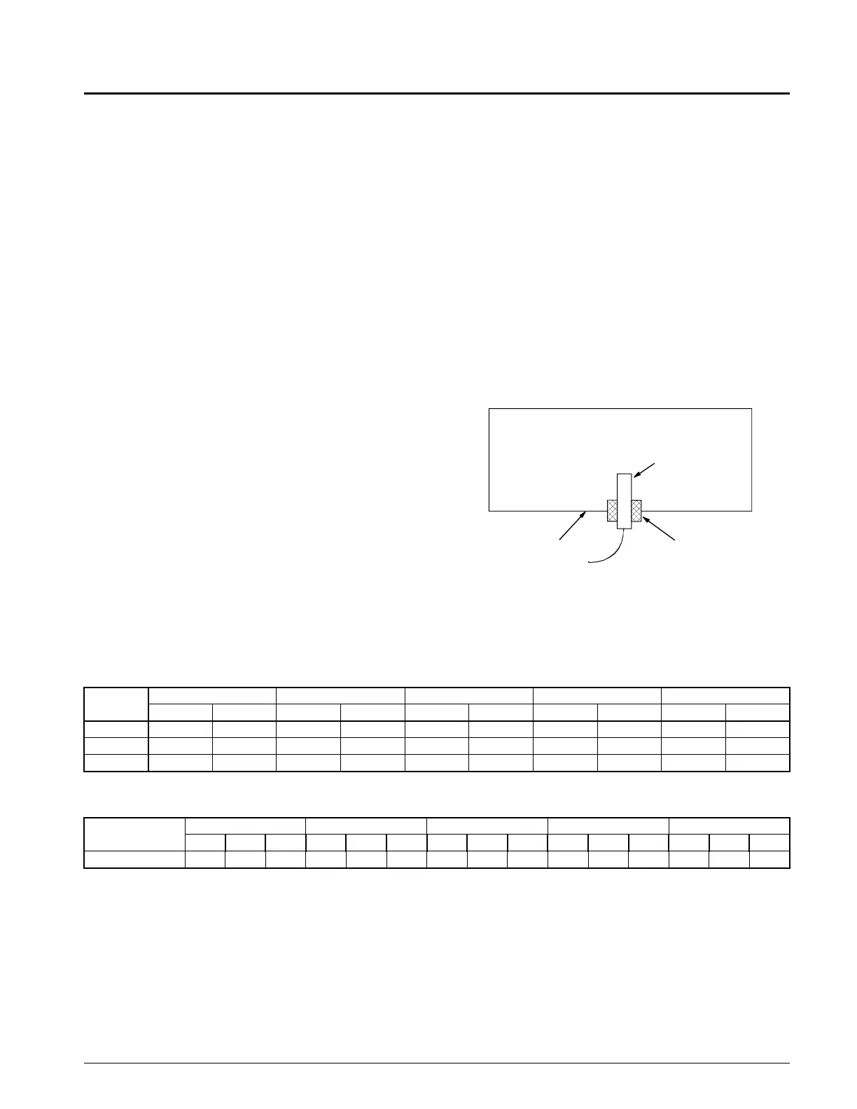
work using a grommet, see Figure 17.
Figure 17. Return/Outside Air Sensor Mounting
The return air sensor is connected to the unit’s input board at
location AI4, see IM710. The outside air sensor is field
wired to terminal strip TB2. The sensor is to be connected at
terminals 124 and 125.
Table 7. Compressor Motors
Table 8. Electric Heaters
Grommet
Sensor
Ductwork
Compressor
HP
208/60/3 230/60/3 400/50/3 460/60/3 575/60/3
RLA LRA RLA LRA RLA LRA RLA LRA RLA LRA
6
17.9 156.0 16.2 156.0 8.1 70.0 8.1 70.0 6.5 54.0
10
31.2 239.0 28.2 239.0 14.1 125.0 14.1 125.0 11.3 80.0
13
35.6 350.0 32.0 350.0 16.0 158.0 16.0 158.0 12.8 125.0
SWP UNIT SIZE
208V/60HZ/3PH 230V/60HZ/3PH 400V/50HZ/3PH 460V/60HZ/3PH 575V/60HZ/3PH
kW MBH FLA kW MBH FLA kW MBH FLA kW MBH FLA kW MBH FLA
018 - 040
27.8 94 77.2 34 116 85.6 25.7 88 37.2 34 116 42.8 34 116 34.2