IOM 1210-1 • MAGNITUDE
®
MODEL WMC CHILLERS 32 www.DaikinApplied.com
operaTIon
Explanation of Tower Control Settings
There are ve possible tower control strategies: (I) NONE,
(II) VALVE SP, (III) VALVE STAGE, (IV) VFD STAGE, and
(V) VALVE SP / VFD STAGE. These control strategies are
selected from the TOWER Setpoint Screen (see Figure 31
on page 31) using Setpoint 2. (In the following pages, “SP”
means “Setpoint.”) An explanation of each control strategy
follows this paragraph. Along with each explanation is a
diagram and graph to help illustrate the control strategy. Note
that these graphs illustrate the default conditions for each
strategy. See "Setting Tower Control Using the OITS Panel"
on page 34 for details on how to set these tower control
strategies.
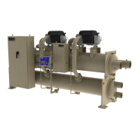
(I) NONE: This control strategy is tower fan staging only.
This is not a recommended strategy. In this mode the
tower fan staging (up to four stages) is controlled by
either the condenser Entering Water Temperature (EWT)
or LIFT pressure (difference between the condenser and
evaporator pressure). Tower bypass or fan speed are not
controlled. See Figure 32 and Figure 33.
Figure 32: TOWER Setpoint - SP2 - (I) NONE
Figure 33: (I) NONE - Temperature vs. Fan Stages
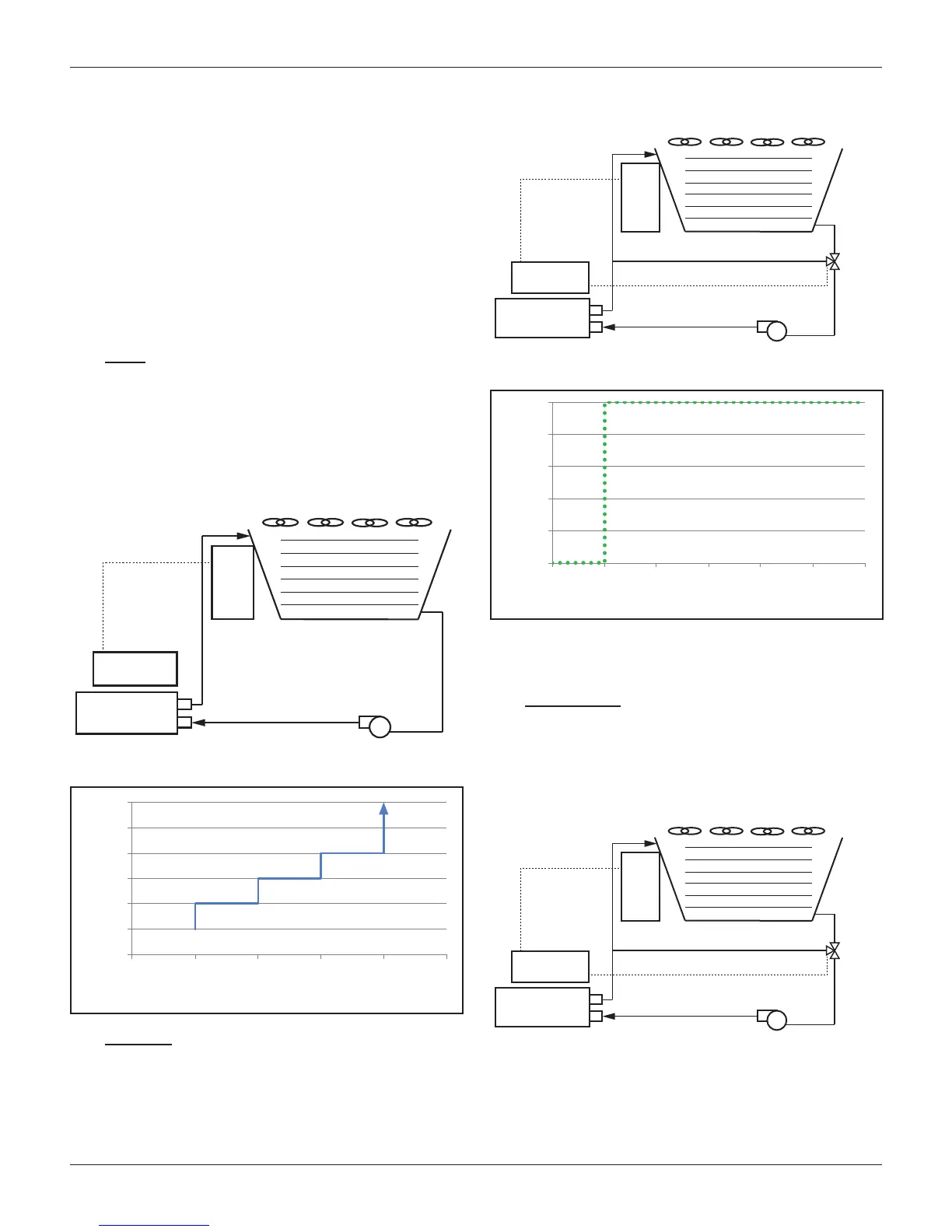
(II) VALVE SP: This control strategy is tower staging (up to
four stages) with a low-limit controlled bypass valve. The
tower fans are controlled as in (I), plus a tower bypass
valve is controlled to provide a minimum condenser EWT.
There is no interconnection between the fan control and
the valve control. See Figure 34 and Figure 35.
Figure 34: TOWER Setpoint - SP2 - (II) VALVE SP
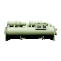
Figure 35: (II) VALVE SP - Valve Opening vs. Temperature
As shown in Figure 35, the default temperature at which the
valve opens completely is 65°F. This temperature is the Valve
SP and is adjustable.
(III) VALVE STAGE: This control strategy is tower staging (up
to four stages) with a stage-controlled bypass valve. In
this mode, the bypass valve controls between fan stages
to smooth the control and reduce fan cycling. See Figure
34 and Figure 37.
Figure 36: TOWER Setpoint - SP2 - (III) VALVE STAGE
Condenser
Cooling Tower
Fan Staging
(Up to 4 fans)
Tower
Control
Panel
MicroTech
®
II
Controller
65
70
75
80
85
90
95
0 1 2 3 4 5
Condenser
Bypass Line
0-10 VDC Signal
Bypass
Valve
Cooling Tower
Fan Staging
(Up to 4 fans)
MicroTech
®
II
Controller
Tower
Control
Panel
0
20
40
60
80
100
60
65
70 75 80
85 90
Condenser
Bypass Line
0-10 VDC Signal
Bypass
Valve
Cooling Tower
Fan Staging
(Up to 4 fans)
MicroTech
®
II
Controller
Tower
Control
Panel