MDS 05-2708A01, Rev. D MDS TransNET I&O Guide 69
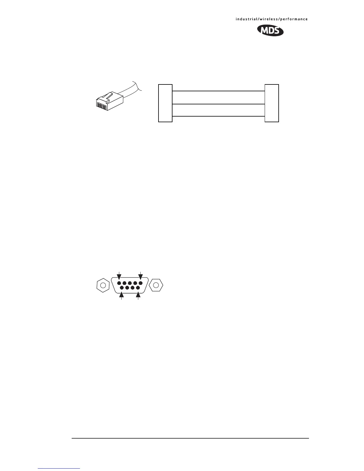
10.3 Diagnostic Interface Connections (RJ-11)
Invisible place holder
Figure 21. RJ-11 to DB-9 Adapter Cable—Wiring Details
NOTE: Only wire pins 4, 5, and 6. Pins 1,2, and 3 are reserved for special functions and
are not normally connected.
10.4 Data Interface Connections (DB-9F)
The DATA connector (Figure 22) is used to connect the radio to an external
DTE data terminal that supports the EIA/RS-232 or EIA/RS-485 (balanced)
format, depending on how the radio was configured at the factory. The radio
supports data rates of 300, 600, 1200, 1800, 2400, 4800, 9600, 19200, 38400,
57600, and 115200 bps (asynchronous data only).
The DATA connector mates with a standard DB-9 plug that is available from
many electronics parts distributors. Table 27 and Table 28 provide detailed
pin descriptions for the DATA connector in RS/EIA-232 mode and
RS/EIA-485 mode, respectively.Pin Descriptions—RS/EIA-232 Mode
Figure 22. DATA Connector (DB-9F)
As viewed from outside the radio
RXD
TXD
GND
2
3
5
DTE
DB-9 FEMALE
(TO COMPUTER)
TXD
RXD
GND
4
5
6
DTE
RJ-11 PLUG
(TO RADIO)
RJ-11 PIN LAYOUT
1
6
5
96
1