Blinking 1 cycle per 4 seconds, 75% duty (operational state)
3 In-Use
OFF Lines idled and unlocked
Yellow, steady ON Lines in use and unlocked
Yellow, blinking yellow, 1 cycle per second, 50%
duty
Locked
7 IN-USE
Amber, steady ON Indicates that the PRI port is in use.
OFF Indicates that the PRI port is not connected.
8 LINK
Green, steady ON Indicates that the PRI port is well connected
Amber, steady ON Indicates that the PRI port is not connected
10ERROR/TROUBLE
Red, steady ON Indicates that the PRI port is not working properly
OFF Indicates that the PRI port is working properly
13ETH1 - Right LED (activity)
Green, blinking, variable rate Network traffic
Green, steady ON No network traffic
OFF Not connected
13ETH1 -Left LED (speed)
OFF 10 Mbps
Green 100 Mbps
Yellow 1000 Mbps
14
ETH2/3/4/5 -Right LED
(activity)
Green blinking, variable rate Network traffic
Green, steady ON No network traffic
OFF Not connected
14
ETH2/3/4/5 -Left LED
(speed)
OFF 10 Mbps
Green 100 Mbps
Yellow 1000 Mbps
Switches
# Switch Description
4 Reset/Default Allows setting the unit to default (known) values. Refer to RESET/DEFAULT Button
Connectors and ports
# Connectors/ports Description
5 SYNC IN 8 KHz TDM synchronisation pulse input
6 SYNC OUT 8 KHz TDM synchronisation pulse output
9 PRI port RJ-45 connector for ISDN-PRI connectivity
13ETH1
A 10/100/1000 BaseT Ethernet RJ-45 connector for access to a LAN, WAN or computer. This port is by default used for uplink /
WAN connection.
14
ETH2-ETH3-ETH4
/ETH5
10/100/1000 BaseT Ethernet RJ-45 connector for access to a LAN, WAN or computer. These ports are used by default for LAN
connections.
11
FXS card with 4 FXS
ports
RJ-11 connector for phone/fax/PBX-FXS connection
12
FXO card with 4 FXO
ports
RJ-11 connector for PSTN/PBX-FXS connection
13
BRI card with 4 BRI
ports
Up to four RJ-48C connectors for BRI connectivity.
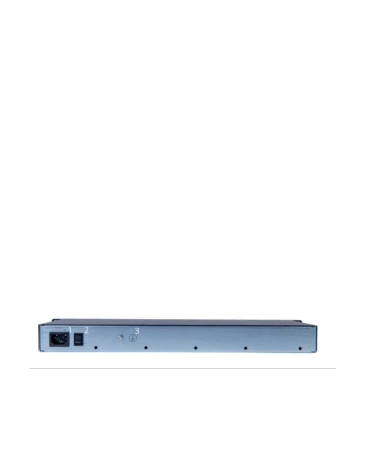
# Description
1 POWER connector
2 Power switch
3 Grounding screw
Top
Installing The Mediatrix Unit
Before you begin
Warning: When installing or replacing the Mediatrix unit, the earth ground connection between the grounding screw on the back of the Mediatrix unit and
an appropriate grounding point in your site must always be made first and disconnected last. This is mandatory to avoid any damage or injuries, even if the
Mediatrix unit is installed in a grounded equipment rack.
Warning: The earth ground cable should be the same size (18 AWG minimum) as the earth cable of the provided power cord. Otherwise, make sure the
earth ground cable meets the standards and requirements of your local electrical code. The type of the cable is likely to have VW-1 or RT1 markings on
the cable.
Warning: The earth ground cable must be firmly and securely connected to the grounding screw on the back of the Mediatrix unit and an appropriate
grounding point in your site: the earth ground cable must remain tightly secured at all times during service and installation.
Warning: Before performing this procedure, you must first read and understand the Safety Recommendations listed in this document.