Do you have a question about the Medion ms-7501M1 and is the answer not in the manual?
Details processor, chipset, memory, LAN, IDE, SATA, and other technical specifications of the mainboard.
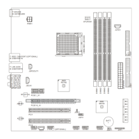
Visual guide showing the placement of components, connectors, and slots on the mainboard.
Instructions for installing the CPU, heatsink, and fan, including important safety precautions.
Steps for installing DDR2 memory modules and configuring Dual-Channel memory mode for enhanced performance.
Guide for correctly connecting the ATX 24-pin and ATX 12V power supply connectors to the mainboard.
Description of external I/O ports on the back panel, including USB, LAN, audio jacks, and PS/2.
Instructions for setting jumpers, specifically the Clear CMOS jumper (JBAT1) for system configuration.
Information on PCI Express and standard PCI slots for adding expansion cards and peripherals.
This document describes the MS-7501M1 (V2.X) Micro-ATX Mainboard, a high-performance and professional desktop platform solution based on AMD® RS780 & SB700 chipsets.
The mainboard supports AMD® Phenom/ Athlon 64/ Sempron processors in Socket AM2/AM2+. It provides various connectors and slots for essential computer components and peripherals, including memory modules, storage devices, expansion cards, and front/back panel I/O. Key features include:
| Brand | Medion |
|---|---|
| Model | ms-7501M1 |
| Category | Motherboard |
| Language | English |