EasyManua.ls Logo

Medion 3500 - User Manual

Medion 3500
27 pages
Print Icon
To Next Page IconTo Next Page
Loading...
Getting Started
1-1
Chapter 1. Getting Started
1
Getting Started
TOPICS
Mainboard Specification 1-2
Mainboard Layout 1-4
Thank you for purchasing the MEDION 3500 (MS-6513 v1.X) Micro
ATX mainboard. The MEDION 3500 is based on Intel
®
Brookdale & ICH2
chipsets for optimal system efficiency. Designed to fit the advanced Intel
®
Pentium
®
4 processors in the 478 pin package, the MEDION 3500 delivers a
high performance and professional desktop platform solution.
Question and Answer IconNeed help?

Do you have a question about the Medion 3500 and is the answer not in the manual?

Overview

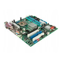
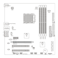
The MEDION 3500 (MS-6513 v1.X) is a Micro ATX mainboard designed for high performance and professional desktop platform solutions. It is based on Intel® Brookdale & ICH2 chipsets, ensuring optimal system efficiency.

Function Description:

The mainboard serves as the central hub for a desktop computer, supporting an Intel® Pentium® 4 processor in a 478-pin package. It provides connectivity for various components including memory, storage devices, expansion cards, and peripherals. The integrated BIOS offers "Plug & Play" functionality for automatic detection of peripheral devices and expansion cards, as well as a Desktop Management Interface (DMI) function to record mainboard specifications.

Important Technical Specifications:

CPU:

  • Support: Intel® Pentium® 4 processor in 478-pin package.
  • Clock Speed Support: 1.5GHz, 1.6GHz, 1.7GHz, 1.8GHz, 1.9GHz, 2GHz, 2.1GHz, 2.2GHz, and up.
  • Core Speed Derivation: CPU Clock x Core/Bus ratio (e.g., 100MHz x 14 = 1.4GHz).

Chipset:

  • Intel® 845 chipset (593 FC-BGA):
    • Supports DDR SDRAM at 200/266MHz operation (DDR200/DDR266).
    • AGTL+ host bus with integrated termination supporting 32-bit host addressing.
    • 1.5V AGP interface with 4x data transfer and 4x fast write capability.
    • 8-bit, 66MHz 4x hub interface to the Intel ICH2.
  • Intel® ICH2 chipset (360 EBGA):
    • Upstream hub interface for access to the Intel MCH.
    • 2-channel Ultra ATA/100 Bus Master IDE controller.
    • USB controller 1.1 (expanded capabilities for 4 ports).
    • I/O APIC.
    • SMBus controller.
    • FWH interface.
    • LPC interface.
    • AC'97 2.1 interface.
    • PCI 2.2 interface.
    • Integrated system management controller.

Main Memory:

  • Slots: Two 184-pin DDR DIMM slots, supporting four memory banks.
  • Capacity: Up to 2GB PC2100/PC1600 DDR SDRAMs.
  • Voltage: Supports 2.5V DDR SDRAM.
  • Module Types: Can install single-sided or double-sided 184-pin DDR DIMM modules. DDR DIMMs have only one notch in the center, ensuring correct orientation.
  • Combinations:
    • DIMM 1 (Bank 0 & 1): S/D, 64MB~1GB
    • DIMM 2 (Bank 2 & 3): S/D, 64MB~1GB
    • Maximum System Memory Supported: 64MB~2GB

Slots:

  • AGP Slot: One AGP (Accelerated Graphics Port) 4x slot (1.5V only). Important: The AGP slot DOES NOT support 3.3V AGP cards. Using a 3.3V AGP card may damage the mainboard.
  • PCI Slots: Three PCI 2.2 32-bit Master PCI Bus slots. The third PCI slot can support two Master devices (supporting 3.3V/5V PCI bus interface).
  • PCI Interrupt Request Routing:
    • PCI Slot 1: INT A#, INT B#, INT C#, INT D#
    • PCI Slot 2: INT B#, INT C#, INT D#, INT A#
    • PCI Slot 3: INT C#, INT D#, INT A#, INT B#

On-Board IDE:

  • Controller: ICH2 chipset provides IDE HDD/CD-ROM with PIO, Bus Master, and Ultra DMA66/100 operation modes.
  • Connectivity: Can connect up to four IDE devices.
  • Hard Disk Connectors (IDE1 & IDE2): 32-bit Enhanced PCI IDE and Ultra DMA 33/66/100 controller. Supports PIO mode 0~4, Bus Master, and Ultra DMA/33/66/100 functions. Connects up to four hard disk drives, CD-ROMs, 120MB Floppy (reserved for future BIOS), and other devices. IDE1 is the Primary IDE Connector, IDE2 is the Secondary IDE Connector.

On-Board Peripherals:

  • Floppy Port: Supports two FDDs with 360K, 720K, 1.2M, 1.44M, and 2.88Mbytes.
  • Serial Ports: Two serial ports (COM A + COM B1), 16550A high-speed communication ports with 16-byte FIFOs.
  • Parallel Port: One parallel port (LPT1) supporting SPP/EPP/ECP mode.
  • USB Ports: Four USB ports (two rear, two front).
  • LAN Jack: One RJ-45 LAN jack for 10/100 Mb/s Ethernet.
  • Audio/Game Port: One audio/game port.

Audio (optional):

  • Controller: C-Media CMI8738 / PCI-6ch supports 2/4/6 channel speakers.
  • Back Panel Audio Ports:
    • Line-in: For external CD player, tape player, or other audio devices.
    • Line-out (Front/Rear): For speakers or headphones.
    • Center/Bass: For a center speaker or bass effect.
  • SPDIF Connectors: SPDIF IN and SPDIF OUT on the back panel for digital audio equipment.
  • Front Audio Line-out Connector (JAUDIO1): For front audio output devices.
  • CD-In Connector (CD_IN1): For CD-ROM audio.

Network:

  • Controller: Realtek RTL8100BL single chip fast 10/100 Mb/s Ethernet controller.

Dimension:

  • Form Factor: Micro ATX.
  • Size: 24.4cm x 22.4cm.

Mounting:

  • Six mounting holes.

Usage Features:

CPU Installation:

  1. Pull the lever sideways away from the socket, then raise it to a 90-degree angle.
  2. Align the CPU's dot/cut edge towards the lever pivot. The CPU will only fit in the correct orientation.
  3. Press the CPU firmly into the socket and close the lever, ensuring the CPU is properly and completely embedded.
  • Warning: Always ensure a heat sink and cooling fan are attached to the CPU to prevent overheating. Overheating can seriously damage the CPU and system.

Memory Installation:

  1. The DDR DIMM has only one notch in the center, ensuring correct orientation.
  2. Insert the DIMM module vertically into the slot and push it in until the golden finger is deeply inserted.
  3. The plastic clips on each side of the DIMM slot will automatically close.
  • Tip: If the module is deeply inserted, you should barely see the golden finger.

Power Supply Connection:

  • ATX 20-Pin Power Connector: Connects to an ATX power supply. Ensure proper orientation and pin alignment before pushing firmly.
  • ATX 12V Power Connector (JPW1): Provides power to the CPU.
  • Precaution: Always ensure all components are installed properly before inserting the power supply connector to prevent damage.

Hard Disk Installation:

  • If installing two hard disks on a single cable, configure the second drive to Slave mode by setting its jumper. Refer to the hard disk documentation for jumper setting instructions.

Fan Power Connectors (C_FAN1):

  • Supports system cooling fan with +12V, using a three-pin head connector.
  • The red wire is positive (+12V), and the black wire is Ground (GND).
  • If the mainboard has a System Hardware Monitor chipset, use a specially designed fan with a speed sensor for CPU fan control.
  • Note: Consult the vendor for proper CPU cooling fan. The PC Alert utility can automatically control CPU fan speed based on CPU temperature.

Front Panel Connectors (F_P1):

  • Provides connections for front panel switches and LEDs: Power Switch, Power LED, HDD LED, Reset Switch.

Front USB Connector (USB1):

  • Provides one front Universal Serial Bus connector for connecting USB devices.

Jumpers:

  • Clear CMOS Jumper (JBAT1): Used to clear system configuration data stored in the CMOS RAM.
    • To clear data: Short pins 2-3 while the system is off, then return to pins 1-2.
    • Warning: Avoid clearing CMOS while the system is on, as it will damage the mainboard.
  • LAN Enable/Disable Jumper (JLAN1): Enables or disables the onboard LAN controller.
  • Center/Bass Setting Jumper (J11 & J12): Used to set which speaker outputs bass when a pair of speakers supporting bass is connected to the Center/Bass audio connector. Invalid if only a single center or bass speaker is connected.

Maintenance Features:

BIOS:

  • Provides "Plug & Play" BIOS for automatic detection of peripheral devices and expansion cards.
  • Includes a Desktop Management Interface (DMI) function to record mainboard specifications.

Overclocking Support:

  • The motherboard is designed to support overclocking.
  • Warning: Ensure components can tolerate abnormal settings. Operating beyond product specifications is not recommended, and damages or risks caused by inadequate operation or beyond product specifications are not guaranteed.

Static Electricity Precaution:

  • Use a grounded wrist strap before handling computer components to prevent damage from static electricity.

Medion 3500 Specifications

General IconGeneral
BrandMedion
Model3500
CategoryMotherboard
LanguageEnglish

Related product manuals