Do you have a question about the Medrad Spectris Solaris EP and is the answer not in the manual?
Essential safety information for operating the system.
Device compliance with relevant standards.
Intended use of the system for contrast media injection in MRI.
Conditions where the system should not be used.
Information regarding legal restrictions on device sale.
Specifies the necessary training for system users.
Lists registered trademarks of MEDRAD and other companies.
Liability disclaimers for modifications and external equipment.
Explains the function and purpose of the EPC.
Defines symbols used on the system and in the manual.
Advises on circumstances that could result in injury or death to patient or operator.
Advises on circumstances that could result in damage to the device.
Overview of the programmable dual syringe system and its components.
System feature to limit pressure during injection to prevent damage.
How the system detects and responds to blockages during injection.
Features protecting against over/under volume or rate conditions.
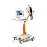
Description and illustration of the Control Room Unit components.
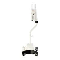
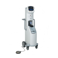
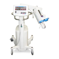
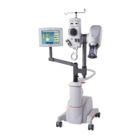
Description and illustration of the Scan Room Unit components.
Detailed illustration and explanation of the Injector Head components.
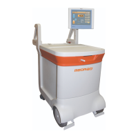
Illustration and identification of the Battery Charger components.
Details on accessories like pedestals and brackets.
Procedure for calibrating the touch screen display.
How to access and navigate the system's help information.
Accessing system settings for configuration and preferences.
Steps for powering on the system and initial diagnostics.
Description of the Main screen interface used for programming and operation.
Guidelines for charging, monitoring, and replacing system batteries.
Procedure for retracting the syringe pistons using the controls.
Step-by-step guide for correctly installing syringes into the injector head.
Instructions for loading contrast and flush solutions into syringes.
Procedure for removing and reinserting a syringe into the injector head.
Overview of programming injection parameters like flow rate and volume.
How to set and adjust flow rate and volume parameters.
How to set the maximum pressure limit for injections.
How to program multiple phases into an injection protocol.
How to use Hold and Pause features in multi-phase injections.
Setting delays before injection, scan, or using a stopwatch.
Setting a delay before the MRI scan begins.
Setting a delay before the injection sequence starts.
Using the stopwatch function to time injections.
Functionality for maintaining venous access with small fluid boluses.
How to initiate and manage the KVO function.
How KVO function interacts with detected occlusions.
Procedure for saving programmed injection protocols for future use.
How to access and load previously saved injection protocols.
Steps to prepare the system for injection after programming.
Selecting between single or repeated injection sequences.
System behavior when insufficient volume is detected during multi-arm sequences.
How to start, hold, resume, and manage injections.
Description of information displayed on the screen during injection.
Indicators and lights on the injector head during operation.
How to stop or disarm the injection process.
How to review past injection parameters and results.
Guidelines for cleaning the injector and its components.
Specific instructions for cleaning the Scan Room Unit components.
Specific instructions for cleaning the Control Room Unit touch screen.
Informational messages displayed briefly on the screen.
Messages requiring explicit acknowledgment via dialog box.
Malfunction messages requiring power removal and service contact.
Daily, monthly, and annual maintenance tasks and recommendations.
Information on services and support provided by MEDRAD.
Daily inspection procedures for the Scan Room Unit.
Daily inspection procedures for the Control Room Unit.
Inspection of wall mount bracket, pedestal, battery charger, and communication link.
Procedures for cleaning the system components safely and effectively.
Functional checkout procedure to verify system operation.
Ensuring labels are legible and verifying system power up sequence.
Verifying programming controls, display contrast, and test injection execution.
Physical dimensions and weight of the Scan Room Unit.
Physical dimensions and weight of the Control Room Unit.
Physical dimensions of the system battery pack.
Physical dimensions and weight of the Battery Charger.
Length specifications for power cords.
Detailed capabilities including syringe volumes, flow rates, KVO, and storage.
Achievable flow rates with specific catheters and system settings.
Accuracy specifications for volume, flow rate, delay, and pressure.
Specifications for low and high speed controls for piston movement.
Compliance with electromagnetic interference and radio frequency interference standards.
Power input voltage and frequency requirements.
DC output voltage of the system's power supply.
Specifications for electrical leakage current and ground continuity resistance.
Operating and non-operating temperature, humidity, and air pressure ranges.
Electrical shock protection, flammable anesthetics, and fluid ingress classifications.
Catalog and part numbers for power cords.
Catalog and part numbers for the battery charger system.
Catalog and part numbers for the battery charger kit.
Catalog and part numbers for the enhanced battery pack.
Catalog and part numbers for the handswitch.
Catalog and part numbers for the optional contrast holder tray.
Catalog and part numbers for mounting systems.
Catalog and part number for the service manual.
Crucial warnings regarding electrical safety, component placement, and tools.
Cautions regarding condensation, voltage, and fiber optic cabling.
List of standard and optional items included in system shipment.
Site requirements and tools needed for system installation.
Overview of electrical and fiber optic connections for installation.
Detailed steps for routing and connecting the fiber optic cable.
Placement of strain relief for fiber optic connectors.
Guidance on routing the fiber optic cable for optimal performance.
Routing the fiber optic cable between rooms through a tuned port.
Steps for connecting power, fiber optics, and handswitch to the Control Room Unit.
Options for mounting the handswitch on the wall, Scan Room Unit, or Control Room Unit.
| Model | Spectris Solaris EP |
|---|---|
| Manufacturer | Medrad |
| Number of Syringes | Dual |
| Syringe Capacity | 200 mL per syringe |
| Injection Rate/Flow Rate | Up to 10 mL/s |
| Pressure Limit | 325 psi (2240 kPa) |
| Power Requirements/Power Supply | 100-240 VAC, 50/60 Hz |
| User Interface/Display | Touchscreen |