Do you have a question about the Medrad ProVis Mark V and is the answer not in the manual?
Covers copyright, trademarks, patents, sale, applicability, and EU directive compliance.
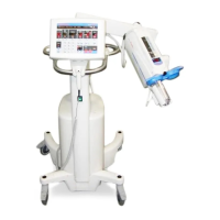
Details the manual's purpose, intended use, and contraindications for the device.
Provides critical safety information including warnings and cautions for system servicing.
Describes how to set and use key operating parameters like Flow Rate, Volume, and Pressure Limit.
Explains the functions of the control panel, including status indicators, arming modes, and program recall.
Outlines recommended procedures and a suggested schedule for system maintenance.
Details procedures for inspecting system components and cleaning the injector.
Covers essential checks for electrical leakage and ground continuity.
Describes the CPU, Clock, Memory, I/O Decoder, and Bus Buffers on the CPU Card.
Explains the Watchdog 1 circuit and the Test Section features of the CPU Card.
Details the bus buffers, display buffers, and I/O decoder on the Input/Output Card.
Explains the Parallel I/O Chip and Counter/Timer Chip (CTC) functionalities.
Covers the Test Decoder and Test Section circuits on the I/O Card.
Describes bus buffers, direction logic, and A/D converter components.
Details A/D converter logic, DAC decoder, and WATCHDOG 2.
Explains PIO3 and System Monitor Flip-Flop inputs and status.
Covers DACs for command/signals, multiplexer, converters, and pot processor.
Details the primary pressure limit circuit and related functions.
Describes flow rate integrator, error amplifier, feed forward, and overpressure circuits.
Covers PPI card bus buffers, decoder, memory, and comparator circuits.
Details analog switches, power-down circuit, RS-232C, and ferrite beads.
Describes keyboard overlay, display card, sentinel, numeric, and LED displays.
Details the controller card's CPU, memory, I/O decoder, and PIO components.
Explains CTC, UART, line drivers/receivers, and display/bus logic.
Covers the DC to DC converter, voltage regulator, and protection circuits.
Details PDCI, brake circuits, overcurrent shutdown, and safety relays.
Explains detectors for zero crossing, ramp generation, trigger, and error conditions.
Covers pressure/velocity amplifiers, limit controls, and motor monitoring.
Details differential amplifier, comparator, drive transistor, and direction control circuits.
Explains ramp generator, overcurrent shutdown, switched voltage, and indicators.
Describes the regulation of +26/-26 VDC, +15/-15 VDC, and +5 VDC supplies.
Details overcurrent and overvoltage protection mechanisms for the +5 VDC supply.
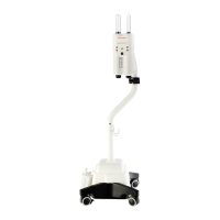
Covers injector head body, syringe heat maintainer, scale overlay, and cables.
Explains drive motors, feedback pots, syringe heat, and forward/reverse circuits.
Details timed enable button and single button disarm functions.
Covers forward/reverse load clamping and the volume remaining display.
Explains turret sensing and mechanical stop position/arm light logic.
Details mechanical stop motor disable and SIP switch settings.
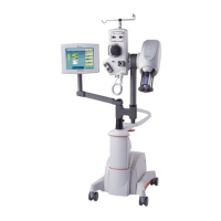
Provides an overview of the ISI and details connector locations.
Describes disarm, handswitch, injector start, injecting, and armed output signals.
Explains ISI card operation for Siemens Z5 interface, including arming and initiation.
Lists required test equipment and describes service access card usage.
Provides general guidelines and a suggested sequence for troubleshooting.
Guides interpretation of Sentinel messages and provides solutions.
Aids in diagnosing conditions without Sentinel messages, like Dead Unit or No Drive.
Procedures for accessing the electronics console of the control unit.
Lists replacement parts for PC boards and general assembly components.
Details specific replacement parts for the injector head assembly.
Lists necessary circuitry parts for CPU, I/O, SCC, PPI, PDCI, MSD, and PSP cards.
Lists necessary circuitry parts for Control Panel and Keyboard Display cards.
Provides instructions and contact information for ordering replacement parts.
Lists the basic tools required for servicing the injection system.
Details the disassembly and reassembly of the control unit's electronics console.
Procedures for removing and replacing PC cards within the control unit.
Instructions for removing and replacing the control panel module.
Procedures for removing and replacing the display card in the control panel.
Instructions for removing and replacing the controller card in the control panel.
Details the process for removing and replacing injector head covers.
Procedures for removing and replacing the syringe heat maintainer.
Instructions for removing and replacing the plunger position potentiometer.
Steps for calibrating and testing the plunger pot after replacement.
Procedures for removing and replacing the mechanical stop potentiometer.
Instructions for removing and replacing the plunger motor drive belt.
Procedures for removing and replacing the plunger drive motor.
Instructions for removing and replacing the mechanical stop motor.
Details for removing and replacing the injector head's control panel.
Procedures for removing and replacing the mechanical stop limit switch.
Instructions for removing and replacing the injector head cable.
Procedures for removing and replacing the oil seal.
Procedure for adjusting the pivot knuckle if the head position is not stable.
Instructions for removing and replacing the power switch.
Steps for converting the system for different line voltages.
Procedure for adjusting the injector for different line frequencies.
Checkout procedure to perform after adjusting line frequency.
| Model | ProVis Mark V |
|---|---|
| Number of Syringes | Dual |
| Manufacturer | Medrad |
| Application | Angiography |
| Flow Rate Range | 0.1 mL/sec |
| Power Supply | 100-240 VAC, 50/60 Hz |
| Display | Touchscreen |