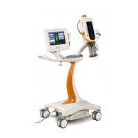
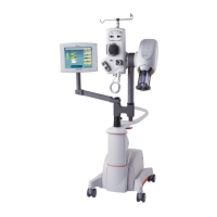
Servo Control Card
7 - 1
Servo Control Card
The Servo Control Card (SCC) serves two primary functions:
• Provide signals that control the Flow Rate and Power
Drive circuits
• Read and interpret information from the head, to control
injection Flow Rate and Pressure [limit].
Refer to Figure 7.1 for a block diagram of the Servo Control Card.
Bus Buffers The control bus is buffered by U12, and the address bus is buffered
by U11. The bi-directional data bus is buffered and controlled by U10,
with direction control coming from direction logic.
Direction Logic Gates U7-U9 control the direction line of U10, controlling the flow of
data to and from the card.
A/D Converter Analog-to-digital (A/D) converter U1 inputs a multiplexed analog sig-
nal, and converts it into a digital word. This process is controlled by
A/D converter logic (U4, U5) and DAC decoder U14. When requested
from the CPU, the converted 10-bit value is gated to the data bus by
tri-state buffers U2 and U3.
A/D Converter Logic Gates U4 and U5 control the A/D converter U1, starting the A/D con-
version when the data is ready, and enabling buffers U2 and U3 to
transfer the converted word to the data bus.
DAC Decoder Decoder U14, with U18 and U6, provide enable signals for the DACs
(digital-to-analog converters) and the MUX (multiplexer). These
enables allow data bus information to be written to the device. The
decoder also provides signals for the A/D converter logic, direction
logic, and Reset pulses for WATCHDOG 2.
WATCHDOG 2 The DAC decoder sends pulses to WATCHDOG 2 (U15) when the
mechanical stop is in position, and “Ready to Inject”. If the Mechani
-
cal Stop takes too long to move into position, the pulses from the
DAC decoder will stop, resulting in a disarm condition. The Sentinel
will then display the message “Mechanical Stop Position Failure”.
PIO3 The inputs to PIO3 (U16) are signals from the Injector Head, Power
Drive Circuit, and the analog portion of the SCC. These inputs
include: Turret switch position sensor, 60 ml indication, and FWD/
REV indication from the Injector Head, Aux Monitor from the PDC,
and an Overpressure Limit signal from the SCC. The status of PIO3
inputs are directed to the CPU through data busses. Outputs from
7
 Loading...