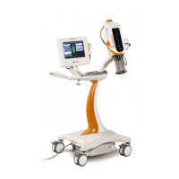
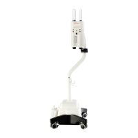
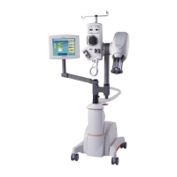
Injector Head
13 - 1
Injector Head
This section describes the components and circuitry in the Injector
Head. The following is a summary of the primary injector head compo
-
nents:
Injector Head Body
Houses the drive and feedback systems for the syringe piston and
automatic mechanical stop.
Syringe Heat Maintainer
Fits on pressure jacket; Maintains syringe fluid temperature at approx-
imately 98.6
0
F (37
0
C).
Injector Head Scale Overlay/Plate
Contains the forward and reverse load controls and indicators that
show armed status, selected syringe size, piston position / Volume
Remaining, and Mechanical Stop position/status.
Turret Sensing Circuit and Limit Switches
Provide indication signals to the console if the turret is out of position,
or the Mechanical Stop is in contact with the Ball Nut Plate.
Head Cable
Connects to the rear of the Main Unit through a screw-on ring type
connector at J21. The Head Cable carries the drive voltages and
other signals which control Injector Head functions. Internal connec
-
tor(s) aid in cable replacement.
13

 Loading...