Disassembly and Reassembly
16 - 17
Injector Head - Plunger Position Pot (continued)
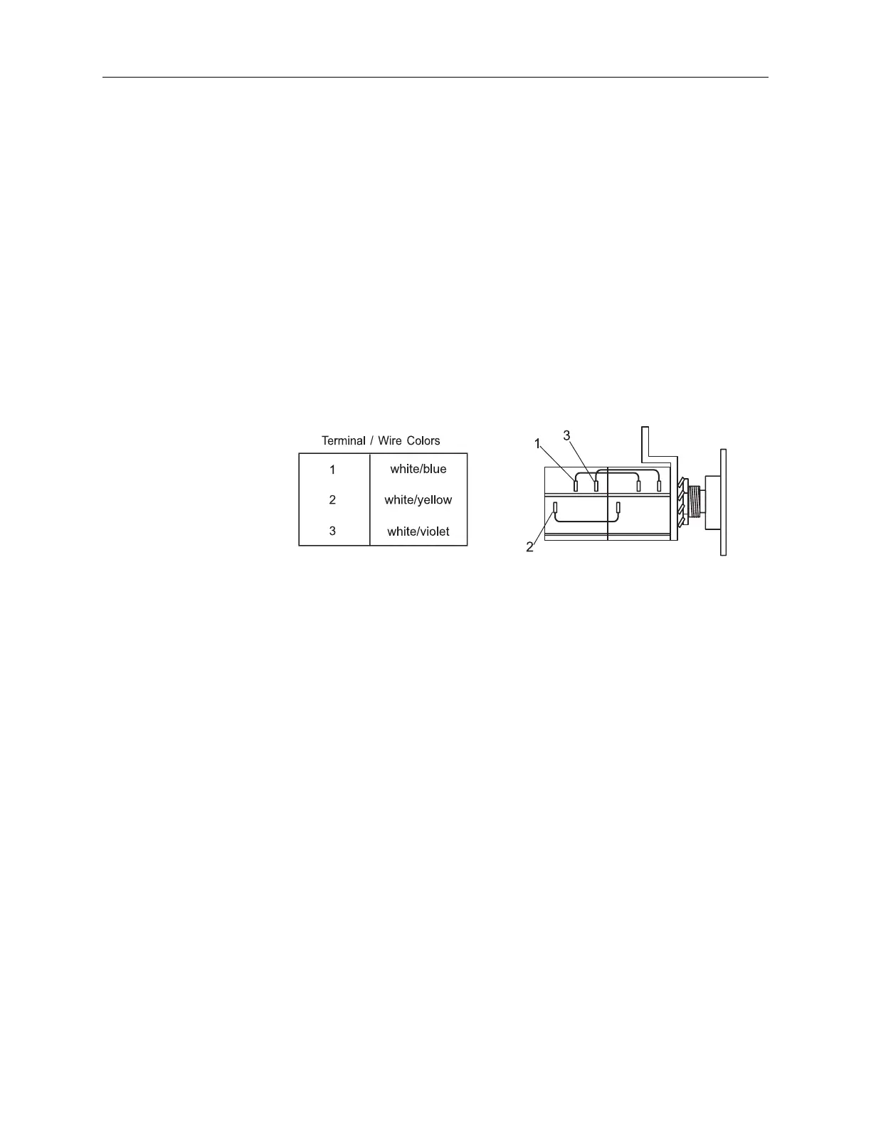
Plunger Pot
Replacement
1. Hold the pot assembly with the gear facing away from you. Turn
the gear counter-clockwise until the gear turns no further. Rotate
the gear clockwise 1/4 turn.
2. Install the new pot assembly with the two screws previously
removed. The pot assembly cannot be tightened until pot calibra
-
tion is complete.
3. Carefully reattach the wires and solder (refer to the chart below).
Ensure that the wires are positioned away from moving parts.
Figure 16.2: Plunger Pot Terminal Identification
4. For the following measurements, connect the DVM ground to ter-
minal 3 on the plunger position pot.
5. Apply power. Disregard any messages that may appear on the
Sentinel. Advance the plunger at least 2 ml to satisfy the plunger
pot test, then reverse the plunger to the rear limit .
6. Measure the wiper voltage on terminal 2 of the plunger position
pot. With the pot disengaged, turn the pot shaft gear until the volt
-
age reads 0.250 VDC +0/-0.020 VDC.
7. Reengage the pot gear, maintaining the voltage as measured in
the previous step, and tighten the pot screws. Ensure that the
gears do not jam.
 Loading...