EN
34
INSTALLATION
UNPACKING
Unpack all the parts and check that nothing
is missing or damaged. If possible save the
packaging until the warranty has expired.
WARNING!
Do not allow children to play with the
product or the packaging material. Keep
the packaging material and all the small
parts out of the reach of children – risk of
suocation.
Contents
2 wheels
1 air lter
1 foot
1 sole for foot
2 hex screws M6
1 at washer Ø 6.4 mm
1 spring washer Ø 6.4 mm
2 wheel screws
1 at washer Ø 10.4 mm
1 spring washer Ø 10.4 mm
1 hex nut M10
TOOLS FOR ASSEMBLY
2 combination spanners, 14 and 17 mm are
required for the assembly (sold separately).
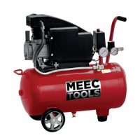
FITTING THE WHEELS
1. Insert the wheel screw (e) through the hole
(3). Now put the wheel screw through the
hole in the compressor. Put the at washer
(f) and spring washer (g) on the screw,
screw on the hex nut (h) and tighten.
2. Fit the other wheel (3) in the same way.
FIG. 2
Always wear ear protection.
The declared values for vibration and noise,
which have been measured by a standardised
test method, can be used to compare dierent
tools with each other and for a preliminary
assessment of exposure. The measurement
values have been determined in accordance
with EN 1012-1:2010.
WARNING!
The actual vibration and noise level when
using tools may dier from the specied
maximum value, depending on how the
tool is used and the material. It is therefore
necessary to determine which safety
precautions are required to protect the user,
based on an estimate of exposure in actual
operating conditions (taking into account all
stages of the work cycle, e.g. the time when
the tool is switched o and when it is idling,
in addition to the start-up time).
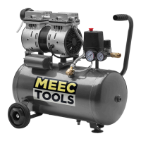
DESCRIPTION
1. Condensation drain plug
2. Air tank
3. Wheel
4. Foot
5. Quick-coupling (outlet pressure)
6. Pressure gauge (outlet pressure)
7. Pressure relief valve
8. Switch
9. Transport handle
10. Pressure gauge (pressure in air tank)
11. Safety valve
12. Air lter
FIG. 1