14
INSTALLATION
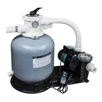
* Install filtration system including pump, filter tank and multiport valve.
* The filter system should be installed as close as possible to the swimming pool and preferably at a level
of 0.50 metres below the surface of the water in the swimming pool. Make sure there is drainage available at the
place where the filter is to be installed.
* PUMP
1.Only qualified, licensed personnel should install pump and wiring.
2.Electrical Contractors Please Note: All 230 volt 50Hz pump must be wired to the main power supply trough an
approved and correctly rated contractor.
3.Allow for gate valve in suction piping.
4.Pump suction and discharge connections have moulded in thread stops, do not try to screw pipe inbeyond these
stops.
* FILTER TANK and MULTIPORT VALVE
1.Loading the sand media. Filter sand media is loaded through the top opening of the filter.
a.Loosen the plastic clamps from tank neck.
b.Cap internal pipe with plastic cap to prevent sand from entering it.
c.We recommend filling tank approximately 1/2 way with water to provide a cushion effect when the filter sand is
poured in. This helps protect the under-drain laterals from excessive shock.
d.Carefully pour in correct amount and grade of filter sand. Be sure center pipe remains centered in opening. Sand
surface should be leveled and should come to about the middle of the filter tank. Remove plastic cap from internal
pipe.
2.Assemble filter control valve to filter tank.
a.Insert filter control valve(with O'ring in place)into the tank neck, taking care that the center pipe slips into the hole
in the bottom of the valve.
b.Place two plastic clamps around valve flange and tank neck and tighten just enough so that the valve may Be
rotated on tank for final positioning.
c.Carefully screw pressure gauge(with O'ring in place)into tapped hole in valve body. Do not over-tighten.
D.Connect pump to control valve opening marked PUMP with hose. After connections are made, tighten clamps with
screwdriver, tapping around clamp with screwdriver handle to help seat valve flange clamp.
3.Make return to pool pipe connection to control valve opening marked RETURN and complete other necessary
plumbing connections, suction lines to pump, waste, etc.
4.To prevent water leakage, be sure all pipe connections are tight.
By-passes filter for circulating water to pool
Used after backwash to flush dirt from valve
Cleaning Filter by reversing the flow
By-passes filter, used for vacuuming to waste or lowering water level
CLOSED Shuts off all flow to filter or pool
RECIRCULATE
WASTE
RINSE
BACKWASH
FILTER
Valve Position
Normal Filtration and Vacuuming
Function
THIS FILTER OPERATES UNDER HIGH PRESSURE. WHEN ANY PART OF THE CIRCULATING
SYSTEM (e.g., CLAMP, PUMP, FILTER, VALVES, ETC.) IS SERVICED, AIR CAN ENTER THE
SYSTEM AND BECOME PRESSURIZED . PRESSURIZED AIR CAN CAUSE THE LID OR VALVE
TO BE BLOWN OFF WHICH CAN RESULT IN SEVERE INJURY, DEATH, OR PROPERTY
DAMAGE TURN PUMP OFF BEFORE CHANGING VALVE POSITION.
TO PREVENT DAMAGE TO THE PUMP AND FOR PROPER OPERATION OF THE SYSTEM.
CLEAN PUMP STRAINER AND SKIMMER BASKETS REGULARLY.
DO NOT UNSCREW SCREWS OF FLANGE CLAMP WHILE PUMP IS RUNNING.
WARNING
!
!
!
!
EM-MV40B VALVE REPLACEMENT PARTS
FILTER & PUMP COMBO
Installation & Operating
Instruction
MEFS10121717
FSF350-6W,FSF400-6W,FSF450-6W
17
18
19
20
21
13
14
15
16
6
12
1
2
3
4
5
7
8
9
10
11
17
18
19
22
21
23
24
25
26
Item Part No Description
1 01013003 Handle(Big)
2 03018008
Pin for Handle
3 01181001 Washer for Handle
4 89280107 M6×30 Screw with Nut for Standard Lid
5 01013004
1.5"Top Mount Valve Standard Lid (Black)
6 02011002 O-Ring for 1.5" Valve Lid
7 01181002 Washer for Spring
8 03014001 Spring for 1.5" Top Mount Valve
9 02011022
O-Ring for 1.5" Valve Rotor
10 01021001 1.5" Valve Rotor
11 02311002
Spider Gasket
12 01013007
1.5"Top Mount Valve Bottom Body Clamp (Black)
13 01013011
1.5" Diffuser
14 02011001 O-Ring for Diffuser
15 01013012 1.5"T op Mount Valve Over Drain Diffuser
16 02011134 O-Ring
17 02011151 O-Ring for 1.5"Connector
18 01013015 1.5"Connector (Black)
19 02011003 O-Ring for 1.5"Union
20 01171153 1.5"Union (A/E)
21 01013017 1.5"Union Nut (Black)
22 01041002 1.5"Union W ith Sight Glass (short)
23 01172026 1.5"Union W ith Sight Glass Holder
24 01111048 Connector for pressure gauge/stopper
25 89021703 Drain Plug with O-ring
26 06011029 Oil Pressure Gauge With O-ring (40Psi)