Do you have a question about the Megger BM80/2 Series and is the answer not in the manual?
Read and understand all safety warnings and precautions before using the instrument.
Follow procedures for circuit isolation, connection handling, and capacitive discharge.
Use correct fuses and ensure test leads are in good condition and insulated.
Follow instructions for fitting the locking or non-locking test button for proper operation.
Understand the meaning of instrument symbols for safe and correct operation.
Employers must ensure valid risk assessments are performed for electrical work involving this equipment.
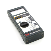
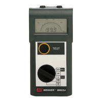
BM80/2 Series testers offer insulation and continuity measurements from 0.01 Ω to 200 GΩ.
Features a large LCD display with combined digital and analogue readings for trend indication.
Instruments offer a choice of locking or non-locking test buttons for user selection.
Ensure the circuit under test is de-energized and isolated before making connections.
Auto-shut Off conserves battery by turning off the instrument after a period of inactivity.
Exercise extreme care when testing voltages above 30V, especially in high energy systems.
Perform insulation tests by pressing and holding the TEST button.
Measures insulation quality by comparing readings at 1 and 10 minutes.
Tests activate automatically when probes make contact, no TEST button needed.
The bleeper indicates continuity below 5 Ω with continuous or short beeps.
Null test lead resistance on continuity ranges to improve accuracy.
Low voltage (5V) low current (20µA) tests for sensitive electronic equipment.
Measure AC or DC voltage; analogue scale can be toggled via TEST button.
Warns of live circuits by defaulting to voltmeter mode and sounding a bleeper.
Check battery status via the Battery Check position; low battery indicated by a symbol.
Replace low battery cells promptly using specified alkaline types.
Check fuse status by pressing TEST on an insulation range; replace with correct type if blown.
Preventive maintenance through insulation testing saves costs and prevents failures.
Identify deteriorating insulation caused by mechanical damage, heat, moisture, etc.
Understand insulation test interpretation, especially trends for operational equipment.
Insulation resistance is calculated using Ohm's Law (R=V/I).
Key factors are current nature and test voltage application time.
Total current comprises capacitive charging, absorption, and conduction/leakage currents.
Details insulation measurement accuracy for various voltage ranges at +20 °C.
Specifies test voltage accuracy and short circuit current limits.
Specifies measurement ranges, accuracy, and test current for continuity and resistance.
Details accuracy for voltage measurements across different ranges and frequencies.
Instruments comply with IEC 1010-1 and EN 61010-1 for double insulation and Category III.
Specifies EMC compliance according to IEC 61326 and details interference effects.
Lists operating conditions, temperature effects, and environmental protection (IP54).
Details fuse type, power source, and physical dimensions of the instrument.
Provides instrument weight and recommended cleaning procedures.
Lists accessories that are supplied with the instrument.
Lists optional accessories available for purchase to enhance functionality.
Lists associated publications, such as the 'A Stitch in Time' booklet.
Handle the instrument carefully due to static-sensitive components on the circuit board.
New instruments are guaranteed for 1 year from the date of purchase by the user.
Unauthorized repairs or adjustments will void the instrument's warranty.
Contact Megger UK/USA and details on approved repair companies and return procedures.
| Brand | Megger |
|---|---|
| Model | BM80/2 Series |
| Category | Test Equipment |
| Language | English |