electrode under test is calculated as R=V/I2 or R=V/(I-I1). The current transducer (ICLAMP) measures I2
and feeds this value back to the instrument.
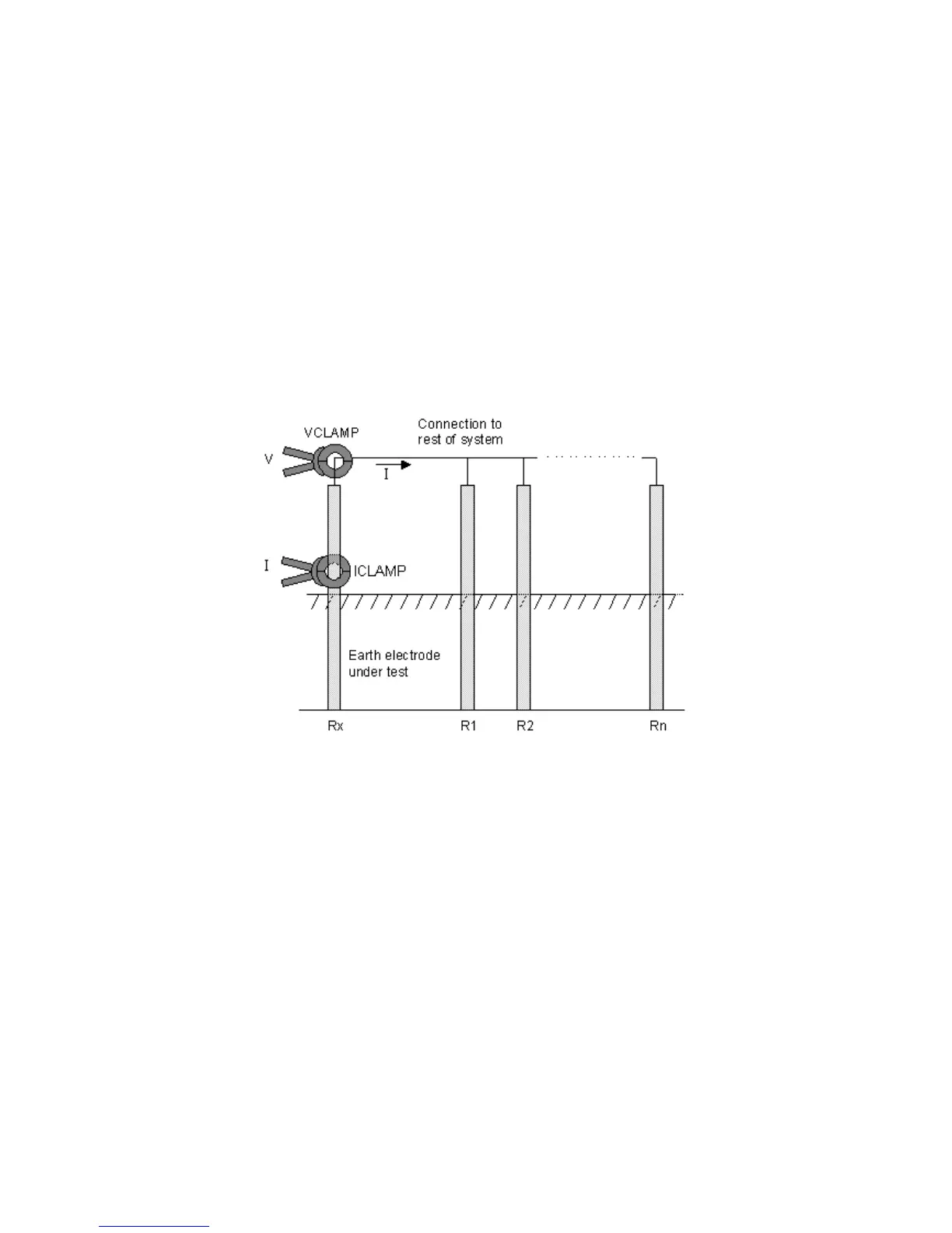
Principle of operation (two-clamp stakeless resistance measurement)
In this example, the electrode under test is connected to a network of other electrodes. It is either
impractical or unsafe to disconnect an individual electrode for testing. Also, there might be insufficient
space to perform a classic three-terminal resistance measurement. The stakeless test method using both
VCLAMP and ICLAMP can be used to obtain a measurement for the electrode under test.
A defined test voltage is injected into the system using the VCLAMP, inducing a current, I, to flow and be
measured by the ICLAMP. The model shown in Figure 7 can be simplified to the resistance of the
electrode under test, Rx and the resistance of the other electrodes in parallel, i.e. R1 || R2 || … || Rn.
Therefore, the current induced by the test voltage is I=V/[R
x
+(R
1
|| R
2
|| … || R
n
)]. It follows that as the
resistance of the other electrodes in parallel approaches zero, then the resistance measured, approaches
the value of the electrode under test.
Figure 7: schematic for two-clamp stakeless resistance measurement

 Loading...