Three-terminal resistance measurement (DET3TA)
1. Ensure the rotary selector switch is in the OFF position.
2. Select the desired test voltage using the procedure in the section on General Operating
Instructions.
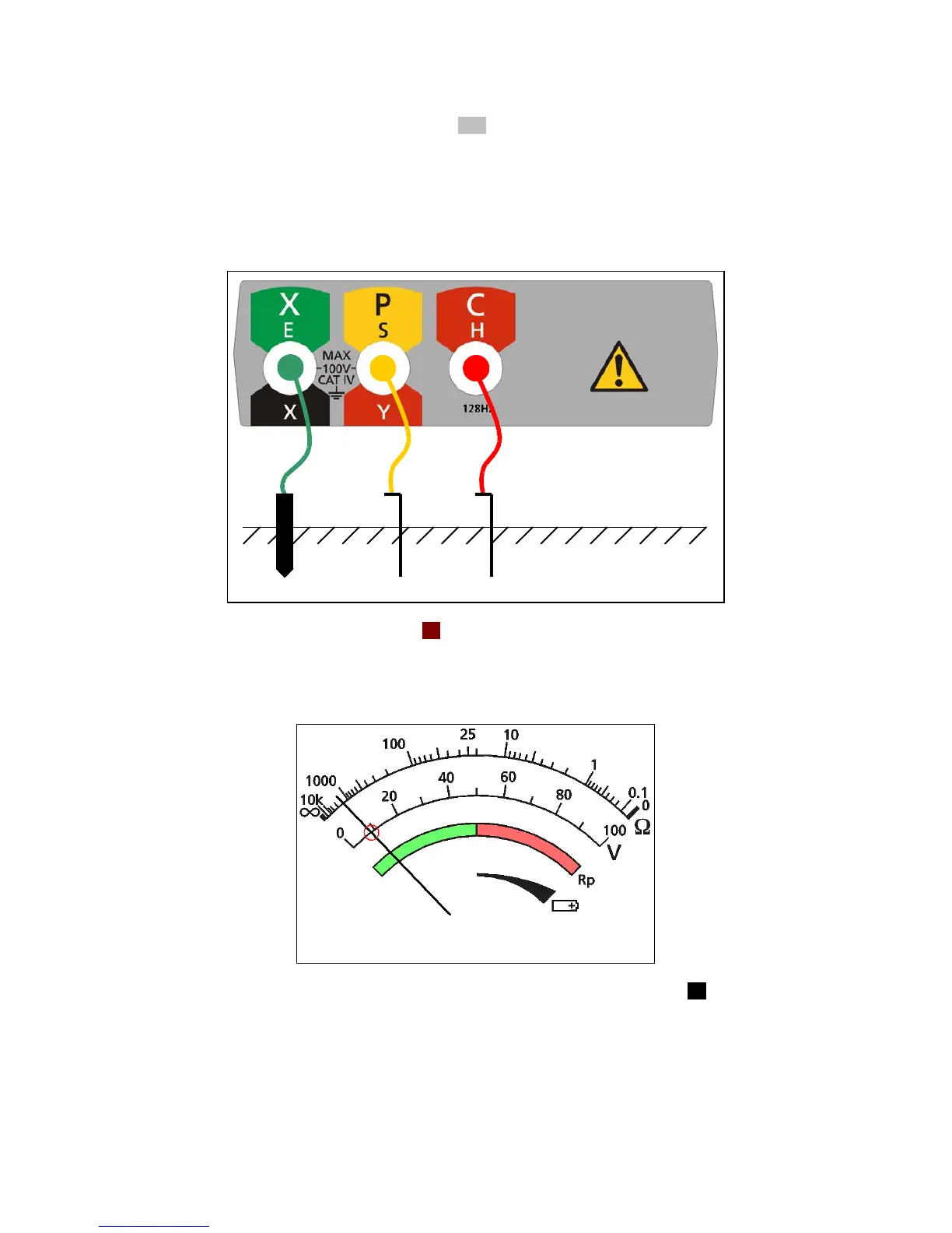
3. Connect the instrument as shown in Figure 20.
Figure 20: instrument connection for measuring three-terminal resistance
4. Set the rotary selector switch to the 3P position.
5. The ground noise voltage will be indicated on the scaleplate as shown in Figure 21.
Figure 21: ground noise voltage indication
6. If the ground noise voltage is less than 40Vpk-pk (14Vrms), press and hold the Rp button.
[Testing will be inhibited if the ground noise voltage exceeds 40Vpk-pk.]
7. The P stake resistance will be indicated on the scaleplate: the needle will move into the green
region (Figure 22) if the P stake resistance is within limits for an accurate measurement and into
the red region (Figure 23) if the P stake resistance exceeds the limits for an accurate
measurement.
 Loading...