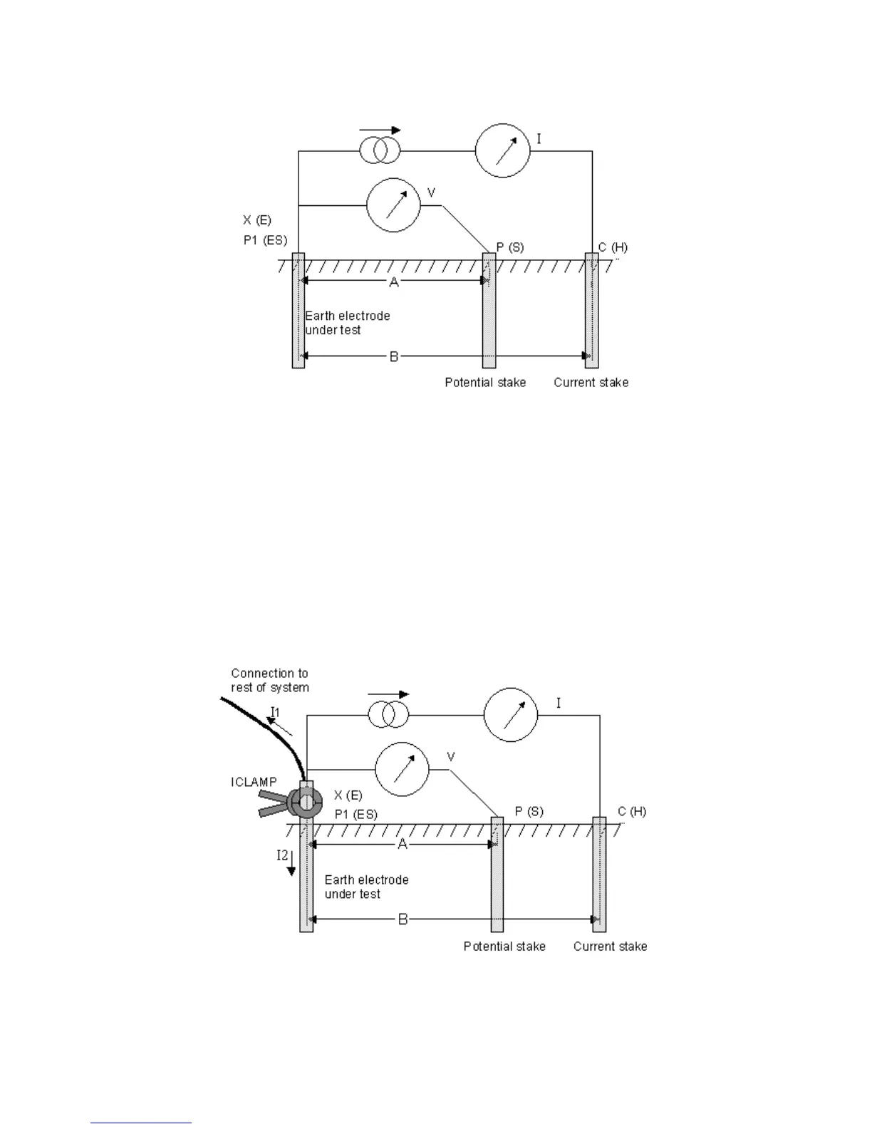
Figure 5: schematic for three-terminal resistance measurement without lead null
Principle of operation (three-terminal resistance measurement using
ART)
The classic three-terminal test method has a disadvantage, namely that the electrode under test must be
disconnected from the system it is supposed to protect in the event of a power system fault. The reason
for this is that the injected test current will take all possible routes to ground and not all of it will
necessarily flow through the electrode under test. In this case, the instrument will make a reading of the
entire earthing network, not just the individual electrode.
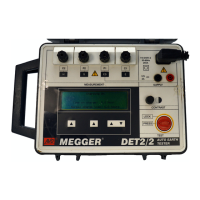
By using a current transducer (the Megger ICLAMP) to measure the current flowing through the electrode
under test as a fraction of the total test current injected, the instrument can determine the individual
resistance. This arrangement is shown in Figure 6.
Figure 6: schematic for three-terminal resistance measurement using
ART without lead null
In this configuration, the injected test current I splits along two paths into I1 (flowing into the connected
earthing system) and I2 (flowing into the electrode under test, i.e. I=I1+I2. The resistance of the