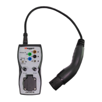
8. Proximity Pilot – PP-Status
With the EVCA210 adaptor connected to the charging point, use the PP State rotary switch to
simulate any of the listed current capabilities of a charging cable.
Selection of cable current
capability
NC (No Cable)
13 A
20 A
32 A
63 A
Note: The EVCA210 does load the circuit but will not draw significant current for this
measurement.
9. Control Pilot - CP State
With the EVCA210 adaptor connected to the charging point, use the CP State rotary switch to
select different simulated vehicle states.
Selection of
Vehicle State
Vehicle State
A Electric vehicle not connected
B Electric vehicle connected, not
ready to charge
C Electric vehicle connected –
ready to charge (ventilation not
required)
D Electric vehicle connected – ready
to charge, (ventilation required)
4 mm CP Signal output ports are located on the top of the EVCA210.
These terminals are connected to the CP and PE conductors of the charging point. The green 4mm
terminal is connected to PE.
For details of the communication protocol please refer to IEC 61851-1 and any documentation
provided by the manufacturer of the charging point under test.
www.megger.com
EVCA210
11
Proximity Pilot – PP-Status

 Loading...