Required electrical tests are as follows:
1. Visual Inspection
2. Continuity of protective conductors and bonding
3. Insulation resistances
4. Earth loop impedance
5. RCD operation
6. Phase sequence (on 3-phase systems)
Required function tests to include:
1. Error handling (Earth fault)
2. Communication
3. Vehicle state
4. Mechanical locking of plug
5. Other tests as appropriate
All leads supplied with the EVCA210 form part of the measuring circuit of the adaptor and must
not be modified or changed in any way.
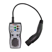
The EVCA210 has the following operational features:
PE Pre-Test to test for the presence of dangerous voltages at the PE terminal, prior to
undertaking any testing, via a touch button electrode with LED lamp indication.
Live phase-neutral indication of all three phases via LED lamps.
Rotary switch providing PP State (Proximity Pilot) for EV vehicle presence and current state
simulation - NC, 13 A, 20 A, 32 A and 63 A.
Rotary switch providing CP State (Control Pilot) for simulation of EV status - A, B, C and D (C
and D both vented and un-vented).
Push button for CP (Control Pilot) Error “E” simulation (CP signal short-circuited to PE)
Push button for PE Error (Earth Fault) simulation.
Five 4 mm ports for connection of suitable test instrument leads (PE, N, L1, L2 and L3)
13 A socket for simple test instrument lead connection.
CP (Control Pilot) signal test sockets. Two 4 mm ports for connection to an oscilloscope.
www.megger.com
EVCA210
7
General Description