Do you have a question about the Meinberg LANTIME M200/GPS and is the answer not in the manual?
General safety instructions, warnings, and protective measures for device operation and installation.
Explains symbols and pictograms used in the manual to indicate hazards.
Guidelines for safe installation, transport, unpacking, and handling of the device.
Instructions for correctly connecting the protective earth conductor for safe operation.
Essential safety precautions to ensure safe operation, including avoiding short-circuits and proper ventilation.
Safety guidelines for maintenance, emphasizing manufacturer-authorized repairs and avoiding moving parts.
Instructions for safely handling and replacing the device's lithium battery, including disposal.
Proper methods for cleaning the device, avoiding liquids and solvents.
Measures to protect against electrostatic discharge (ESD) for sensitive components.
Information on product recycling and disposal according to WEEE directive.
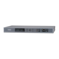
Provides physical dimensions and mounting details for the LANTIME chassis.
Details on how to connect the external ground connection to the housing.
Explains the meaning of the status LEDs (Alarm, Network, Time Service, Ref. Time) on the front panel.
Specification for the AC power inlet, including fuse, voltage, and current ratings.
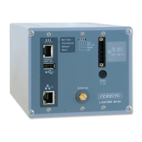
Details on the Ethernet network port, including signal, data rate, and connection type.
Information on the USB interface and its uses for storage and configuration.
Instructions for connecting a serial terminal for device configuration via CLI.
Describes the function of various status LEDs on the device.
Specifications for the antenna input, including dielectric strength, receiver type, and frequency.
Explanation of the LEDs related to the GPS receiver status.
Guidance on choosing an optimal location for the GPS antenna for best reception.
Instructions for physically mounting the GPS antenna and connecting the cable.
Diagrams showing the physical dimensions of the GPS antenna and its accessories.
Technical specifications for the GPS antenna, including power, frequency, and protection class.
Details on different antenna cable types, their attenuation, and maximum lengths.
Information on handling antenna line short-circuit conditions and associated display messages.
Technical details and features of the MBG S-PRO surge protection device.
Visual representation of the physical dimensions of the MBG S-PRO surge protector.
Instructions for installing and grounding the MBG S-PRO surge protection unit.
| Model | LANTIME M200/GPS |
|---|---|
| Time Source | GPS |
| Power Supply | 100-240 V AC, 50/60 Hz |
| Operating Temperature | 0°C to +50°C |
| Mounting | 19" rack mount |
| Form Factor | 1U Rackmount |
| Network Interfaces | 2 x 10/100/1000 Mbit/s Ethernet ports |
| Dimensions | 19" rack mount, 1U height |
| Output | NTP, PTP |
| Protocols | NTP, PTP, HTTP, HTTPS, SSH, SNMP |
| Time Accuracy | Better than 1 µs to UTC |