Do you have a question about the Memmert BE 500 and is the answer not in the manual?
Explains hazard symbols and their meaning in the manual.
Provides essential safety guidelines for operation and load handling.
Lists key technical specifications like volume, power, voltage, and weight.
Ensures temperature sensors are correctly positioned before first use.
Explains how to set temperature using digital display and knobs.
Addresses common malfunctions, error codes, and resetting procedures.
Checklist for identifying and rectifying common faults, often requiring a service engineer.
Information on specific error codes (E1 to E4) displayed by the unit.
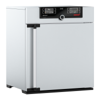
This document provides operating instructions for Memmert electronically controlled ovens, specifically models UE/BE 200-800 and ULE 400-800. These ovens are manufactured in Germany using advanced production techniques and high-quality materials, ensuring a technically superior and fully developed product. Each oven undergoes extensive testing at the factory to guarantee reliable performance. To ensure many years of satisfactory service, it is crucial to observe the operating and maintenance instructions provided.
Memmert appliances from the UE, BE, and ULE series are electrically heated and feature continuous temperature control via a microprocessor-controller with pulse package control. The power module is safely isolated from the controller electronics by an optocoupler, adhering to VDE regulations for electrical isolation. Temperature measurement is performed using a PT 100 (4-wire) sensor, offering a temperature set accuracy of 0.1°C for BE types and 1°C for UE and ULE types.
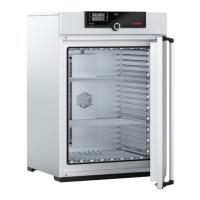
UE and BE series ovens utilize natural air circulation, while ULE series ovens incorporate fan-assisted circulation for enhanced temperature distribution. The door is opened by pulling the door knob.
These ovens are designed for a wide range of applications requiring precise temperature control. They are not explosion-proof and are therefore unsuitable for drying, evaporating, or burning-in substances whose solvents may form an inflammable or explosive mixture with air. It is essential to prevent the formation of such mixtures both inside the cabinet and in its immediate vicinity.
General Safety: Users must strictly observe the physical and chemical properties of the load, such as inflammation temperature, to prevent damage to the load, oven, or surroundings. Severe dust formation inside or around the cabinet can lead to fine dust deposits within the equipment, potentially causing short-circuits. Adequate precautions against excessive dust formation are necessary.
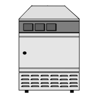
Installation: Units can be placed on the floor or a table/bench. Models 500-700 may require a subframe (accessory). Ensure at least 150 mm clearance between the back of the oven and the wall, and not less than 200 mm between the ceiling and the oven. After horizontal setup, the door can be adjusted if needed. Model 800 is movable and features lockable front castors, which must always be adjusted to the front for locking to ensure stability.
For ovens up to model 700, metal mounting brackets are available for wall fixation. These brackets come with an incombustible plate. The dimensions of the fixing screws depend on the total weight of the equipment and load, as well as the wall quality.
For stacking two ovens of the same size, the oven with the lower working temperature should be placed at the bottom. The front feet of the top oven are replaced with those supplied with the stacking device. The top cover of the bottom oven is removed, and a drilling jig is used to mark and drill a 4.2 mm diameter hole in the back corner. Centering cylinders are then fixed with screws, and the top cover is re-fixed. Model 700 can only be stacked with an intermediate frame.
Temperature Setting and Overheat Safety: To operate, set the mains supply switch (rotary switch No. 2) to position I. The green pilot lamp (No. 3) indicates "unit ready for use," and the yellow pilot lamp (No. 4) indicates "heating on." The desired temperature is selected using knob 1 while pressing key 6. While key 6 is depressed, the digital temperature indication (7) switches to setpoint selection, indicated by a blinking point. The setpoint can be changed quickly in large steps or slowly in single steps. After releasing key 6, the setpoint is shown briefly before switching to the actual value. The scale can be locked with screw 1a to prevent unintentional changes.
The adjustable overheat controller (TWW, class 3.1) is set with knob 9 above the selected working temperature (e.g., 5°C). This scale can also be locked with screw 9a. The selected setpoint of the TWW is always displayed on temperature display 12. Once steady conditions are reached, the desired temperature can be read on the digital display 7. For optimal protection of thermal-sensitive loads, it is advisable to reset the TWW after steady temperature conditions are reached, so it is just not operating. This reduction should be done slowly, step-by-step, slightly above the actual steady temperature (approx. 3°C, or 0.5°C for incubators).
If the operating temperature is exceeded due to a fault in the temperature control circuit, the TWW takes over control, indicated by the flashing red signal lamp 5. In such cases, the unit must be checked immediately by a qualified electrician.
Timer Operation (Special Equipment): For operation with a timer, set the main supply switch (rotary knob No. 2) to position I and the required time period with rotary knob No. 10. The unit automatically turns off when the elapsed time runs down. Timers can be retrofitted by a service engineer, with full instructions provided.
For a program timer, adjust program timer 22 to the actual time. The operation time of the temperature regulator is adjusted by pushing single switch buttons (red section visible). If buttons are not pushed (black section visible), the temperature regulator is out of service, and heating elements are cut off. Set the main switch (rotary knob No. 2) to position I. The green pilot lamp (No. 3) indicates readiness, and the yellow pilot lamp (No. 4) indicates heating status. Set the temperature as described for units with adjustable overheat controllers. Heating and cooling times depend on the load and ambient temperature. The program runs continuously, and manual switching off is done with main switch No. 2 to position 0.
For program timers with a final switching-off timer (from model 500), select the temperature as described under "Operation with program-timer." Timer 19 is used for final switching off and must be set as described under "Operation with timer." The oven switches off when the set time has elapsed.
Adjustable Air Turbine (Special Equipment): The speed of the air turbine can be continuously varied with rotary button No. 12. The air turbine can be disconnected by switch 13.
Fresh Air Ventilation: The amount of fresh air entry is adjusted by slide control knob No. 8. In position 0, the flap is closed, providing virtually no through ventilation. Opening the flap renews the air in the working space to a limited extent. Maximum fresh air entry is achieved at position 6, though this does not signify a complete air change. Intermediate positions vary the degree of ventilation.
Loading Guidelines: For correct operation and uniform temperature distribution, free air circulation must be maintained throughout the oven. Contents should not be packed tightly or placed directly against heating ribs. A small air gap between the rear of the working chamber and the shelf is necessary for better air circulation. If the load is packed tightly and the ventilation slide is fully open, the unit may control at a temperature below the set thermostat. In such cases, it may be necessary to increase the thermostat setting until the desired temperature is shown on the digital display 7.
Important for Loading: These units must not be used for drying or warming substances that generate ignitable vapors when mixed with air. They must never be operated in areas with an explosive atmosphere.
Memmert appliances require minimal servicing. It is recommended to lubricate the moving parts on the doors (hinges and door lock) with a thin silicone grease once a year (or four times a year with continuous use). Any work requiring the opening of the unit due to a malfunction must be performed by a qualified service engineer.
Readjusting the Door: A tightly closing door is essential. Memmert ovens ensure a perfect seal. Over time, the flexible seal material may acquire a permanent set, necessitating adjustment of the hinge or locking plate. To adjust the door, release screw No. 12 (secured with glue; loosen with a 2 mm inner hexagon key wrench). The door can be adjusted by turning the eccentric 13 in the direction of the arrow (using a screwdriver). Tighten screw No. 12 again. The upper part No. 14 of the door hinge can also be moved slightly in the direction of the arrow after releasing the two screws at the top or bottom. The locking plate can be readjusted in the direction of the arrow after releasing screw No. 15. Ensure the cover is screwed down tightly.
Cleaning: Regular cleaning of the easy-to-clean interior prevents residues that could impair the oven's appearance and function. The unit can be cleaned with commercial stainless steel cleaning agents. Objects prone to rust must not be placed inside the interior, as rust sediments can contaminate the interior or external casing. If rust stains occur on the interior surface due to contamination, the affected areas must be cleaned and polished immediately.
Troubleshooting: A checklist for rectifying faults is provided, which should only be addressed by a service engineer. Common issues include:
In case of any malfunction indicated by displays E1 to E4, please inform the Memmert service department.
The details in these Operation Instructions must be carefully observed to ensure satisfactory operation. Warranty and claims for damage are excluded if these instructions are disregarded. Memmert reserves the right to make changes in technical specifications, and dimensions are subject to confirmation.
| Voltage | 230 V |
|---|---|
| Frequency | 50/60 Hz |
| Power Consumption | 250 W |
| Power Supply | 230 V, 50/60 Hz |
| Heating Method | Convection |
| Shelves | Stainless steel |