98
2. HARDWARE INSTALLATION
2.1. Setting up your recorder for use
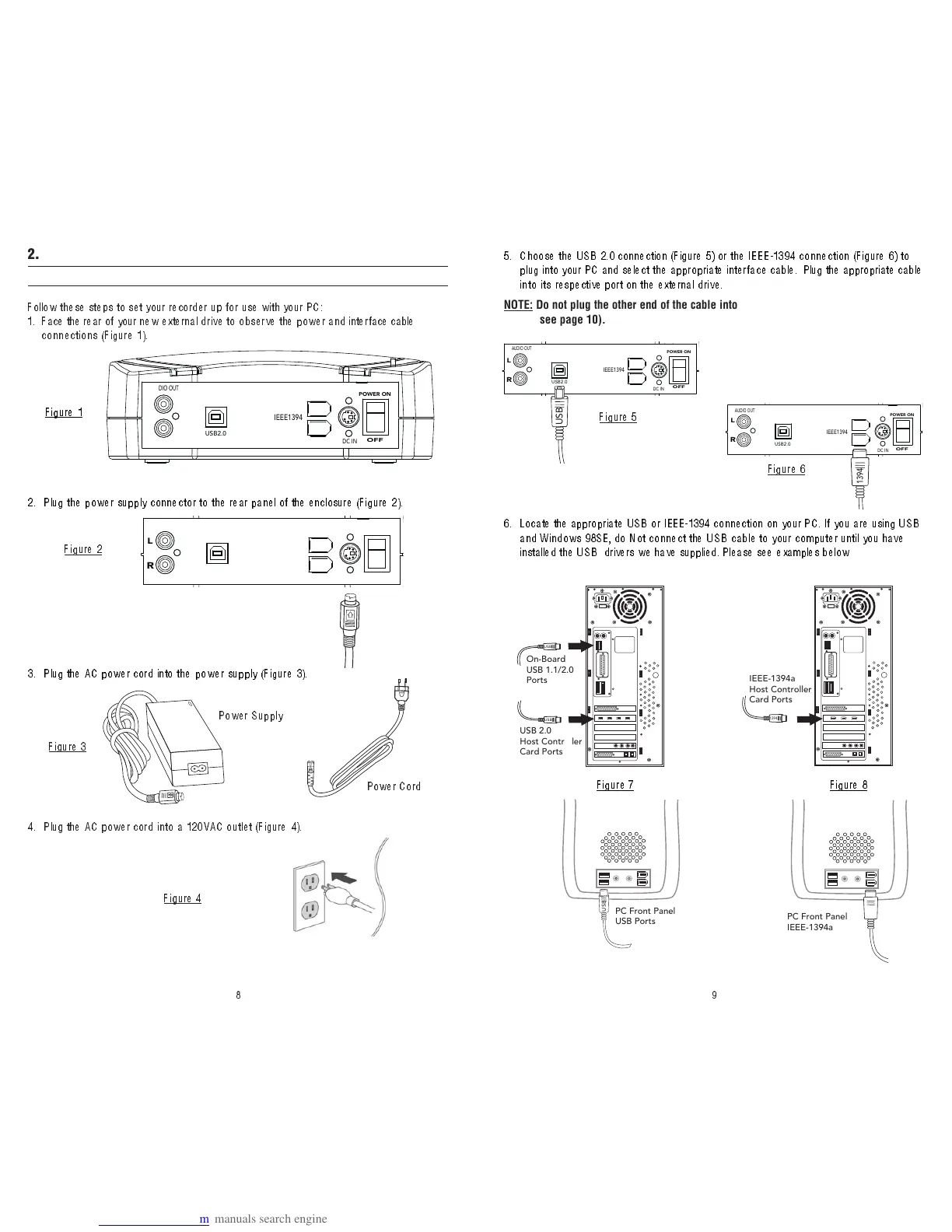
Follow these steps to set your recorder up for use with your PC:
1. Face the rear of your new external d ri ve to o bs er ve the pow er and inter face cable
connections (Figure 1 ).
AUDIO OUT
USB2.0
IEEE1394
DC IN
POWER ON
OFF
Figure 1
2. Plug the power supply connector to the rear panel of the enclosure (Figure 2) .
3. Plug the AC power cord into the power supply (Figure 3).
Figure 2
Figure 3
Power Supply
Power Cord
4 . Plug the AC power cord i n t o a 1 2 0 VAC outl et (F ig ure 4 ) .
Figur
e 4
AUDIO OUT
USB2.0
IEEE1394
DC IN
POWER ON
OFF
L
R
AUDIO OUT
USB2.0
IEEE1394
DC IN
POWER ON
OFF
L
R
5 . Choose the USB 2.0 connection (Figure 5) or the IEEE-1394 connection (Figure 6) to
plug into your PC and select the appropriate inter face cable. Plug the appropriate cable
int o i t s respective port on t he ext erna l d r iv e .
NOTE: Do not plug the other end of the cable into your PC yet, this step will come later
(see page 10).
Figure 5
Figure 6
AUDIO OUT
USB2.0
IEEE1394
DC IN
POWER ON
OFF
L
R
AUDIO OUT
USB2.0
IEEE1394
DC IN
POWER ON
OFF
L
R
6. Locate the appropriate USB or IEEE-1394 connection on your PC. If you are using USB
and Windows 98SE, do Not connect the USB cable to your computer until you have
installed the USB drivers we have supplied. Please see examples below
Figur
e 7 Figure 8
USB
USB
On-Board
USB 1.1/2.0
Ports
USB 2.0
Host Controller
Card Ports
1394
IEEE-1394a
Host Controller
Card Ports
USB
PC Front Panel
USB Ports
PC Front Panel
IEEE-1394a Ports