MEMPHIS PRO ASSEMBLY INSTRUCTIONS
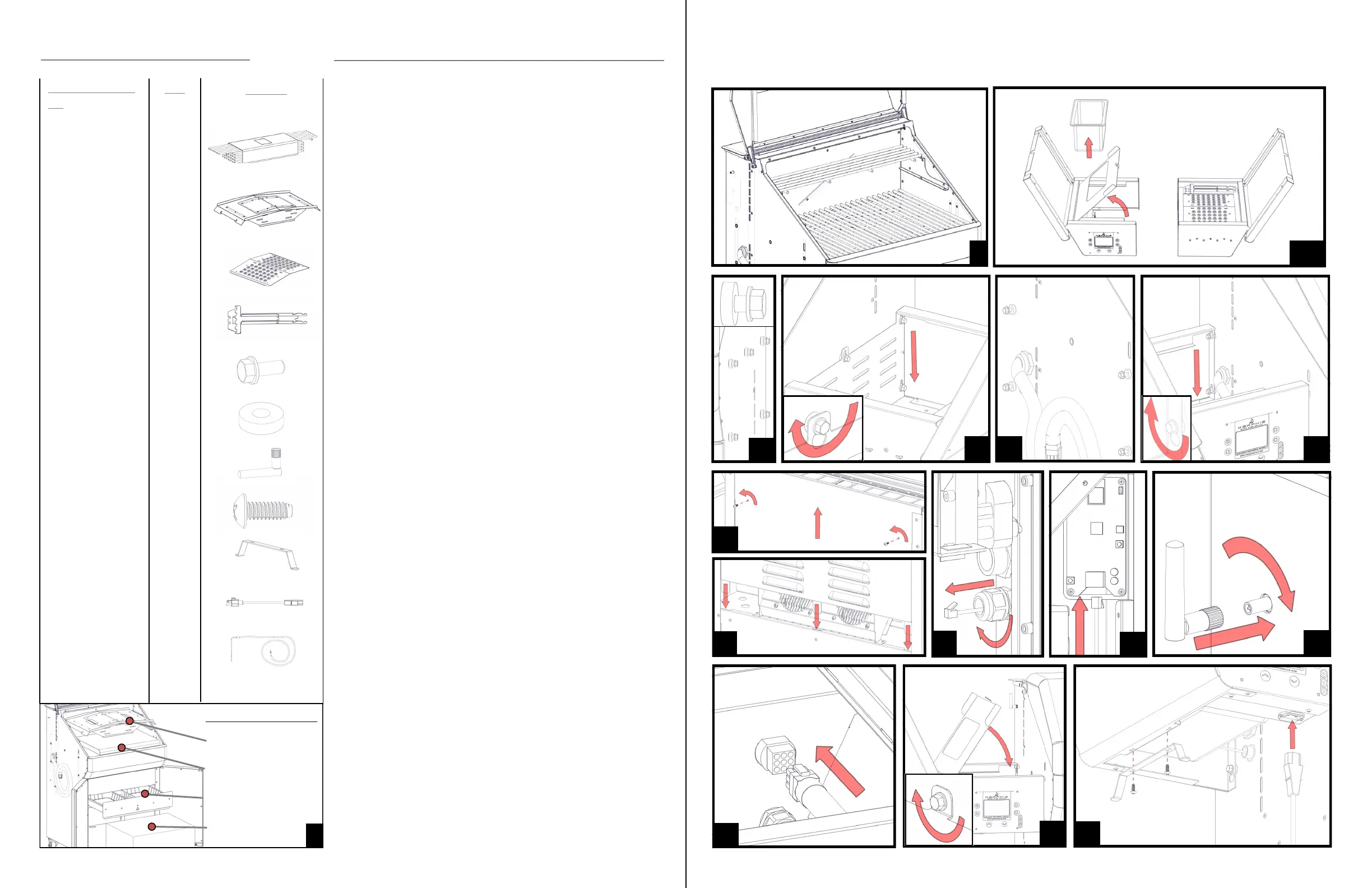
1: Remove both shelves, the hardware kit, Flavorizer, and grate kit from the grill.
The controller shelf will be in the grill hood underneath the grate kit and
Flavorizer. To do so, cut the 4 zipties holding the Flavorizer in place.
Remove all laser lm on the grill. This is a peel-able plastic left on to
protect your grill from scratches during manufacturing and transit.
Remove all laser lm and laser etch lines with the included stainless
steel wipes, WD40, or olive oil. Once a grill has been heated up it is
very difcult to remove this lm, be sure to check your grill thoroughly
before rst burn.
2: Replace the Flavorizer and place 4 small grates on the lower level and the long
grate on the upper level.
3: Remove the Direct Flame Insert, Genie Tool, and included pellets from the
non-controller side shelf (right).
4: Remove the shelf pan and pan tray from the controller side shelf (left) before
installation.
5: Install 5 shelf bolt (#5) and shelf washer (#6) pairs into the right side of the
grill. Leave approximately 1/4” of the bolts sticking out so that the shelf can slide
onto them.
NOTE: ALWAYS HOLD SHELVES FROM THE BOTTOM AS THE
SHELF TOP FLIPS OPEN!
6: Slide the shelf onto the bolts, press down on the shelf to secure into the
keyway. Tighten bolts using 3/8” wrench, socket, or adjustable wrench.
7: Repeat steps 5 and 6 for the left side of the grill. The left side only requires 4
bolt and washer pairs for this step.
8: Lift the hopper lid. Remove the two screws from the back panel as shown and
lift up on the back panel.
9: Route the Ethernet cable connected to the controller side shelf into the back of
the grill. The port is located just below the main wiring harness on the controller
side of the grill. Tighten the strain relief once you have pulled approximately 3
feet of cord into the grill.
10: Route the Ethernet cable behind the auger motor and connect to the Wi-Fi
card. Note: The tab on the Ethernet cord goes towards the front of the grill.
11: Attach the included antenna to the grill by twisting in a clockwise motion. The
antenna will be included in the hardware kit located in the grease tray.
12: Replace the back panel as shown. There are 3 metal tabs on the bottom of the
panel that must be slid into place before securing. Reinsert and tighten included
screws.
13: Attach the main grill harness to the plug in the back of the grill controller box.
14: Reinsert and fasten the shelf pan and shelf tray as shown using the last shelf
bolt included in the hardware kit. Note: This bolt does not get a washer.
15: Attach the cord wrap with included screws found in the hardware kit. Plug in
the grill using the included power cord.
COMPLETE THE STEPS BELOW IN NUMERICAL ORDER, REFERENCE THE SAME
NUMBERED DIAGRAM AND HARDWARE COMPONENTS FOR CLARIFICATION.
2 3-4
5
6
7
7
8
12
10
9
11
13
14
15
HARDWARE COMPONENTS
DESCRIPTION/PART
NO.
1) Grate Kit
VG4409
2) Flavorizer
VG4403
3) Direct Flame
Insert
VG4407
4) Genie Tool
VG1594
5) Shelf Bolt
DS2311
6) Shelf Washer
VG0216
7) Antenna
VG9025
8) #10 Screw
DS2185
9) Cord Wrap
VG0560
10) Power Cord
VG0911
11) Meat Probe
VG0956
QTY:
1
1
1
1
10
9
1
2
1
1
1
PICTURE
Left Shelf
Hardware Kit
Right Shelf
Packaging Locations
1
Flavorizer
 Loading...