Page 10
• Connect Only similar batteries together
in a battery bank. Do not connect old
to new, flooded to gel cells, or batteries
with different capacities.
• Use extension cables with the specified
gauge (or thicker).
6’ or less: 4 AWG; 6-10’: 2 AWG
RISK OF EXPLOSIVE GASES.
• Assemble the battery bank in a clean,
well-ventilated location, away from igni-
tion sources and flammable materials.
• To reduce risk of battery explosion, follow
these instructions and those published
by the battery manufacturer and manu-
facturer of any equipment you intend to
use in vicinity of a battery. Review cau-
tionary markings on these products.
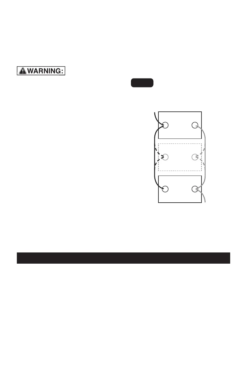
CONNECTING THE BATTERIES
IN PARALLEL
1.
First, connect all of the positive termi-
nals to each other.
2.
Next, connect all of the negative ter-
minals to each other.
3.
Connect the negative and positive
output cables to opposite ends of the
bank. Do not allow the output cables
to touch one another.
4.
Test the voltages at the output cables,
to make sure that the battery bank is
correctly wired.
5.
If the voltage is higher than 13 volts,
part of the battery bank is proba-
bly connected in series (a negative
terminal of one battery attached to
a positive terminal of another) instead
of in parallel.
6.
Carefully examine the diagram and
correct the wiring before attaching to
the converter.
7.
Make sure the converter’s switch is
set to OFF (O).
8.
Connect the output cables from the
battery bank to the converter.
12V
lead-acid
battery
200 Ah*
Connect additional
12V 200 Ah*
lead-acid
batteries here
to increase capacity
12V
lead-acid
battery
200 Ah*
-
+
+
-
+
-
Example:
12V/400 Ah
†
BATTERY BANK
OUTPUT
to NEGATIVE
converter
terminal
OUTPUT
to POSITIVE
converter
terminal
Fig. 4
†Bank Capacity =
(single battery capacity) x (# of batteries)
400 Ah capacity is for (2) 200 Ah batteries.
*200 Ah batteries shown for illustration
purposes.
11. OPERATING INSTRUCTIONS
1.
Connect the converter (see Connect-
ing Converter Cables section.
2.
Switch the converter’s ON/OFF switch
to the ON (I) position.
3.
The GREEN LED indicator will light, indi-
cating the converter is receiving power.
4.
Switch the converter’s ON/OFF switch
to the OFF (O) position. (The GREEN
LED may flash briefly and/or the inter-
nal speaker may make a brief “beep”.
This is normal.)
5.
Make sure the device to be operated
is turned OFF.
6.
Plug the device into the converter’s
AC outlet.
7.
Switch the converter’s ON/OFF switch
to the ON (I) position.
8.
Turn the device on.
9.
To disconnect, reverse the above pro-
cedure.
NOTE: If more than one device is to be
powered, start one device at a time, to
avoid a power surge and overloading the
converter. The surge load of each device
should not exceed the converter’s Con-
tinuous Operation wattage rate.