Do you have a question about the Meraki Cisco MS425 Series and is the answer not in the manual?
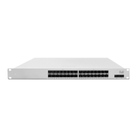
Diagrams showing the front panel layout for the MS425-16 and MS425-32 series.
Explains LED status and meaning for front panel indicators, including restore and status functions.
Steps to log in, create/select a network, and add switches to the Meraki dashboard.
Details how switches can be assigned IP addresses dynamically via DHCP.
Explains how to assign static IP addresses using a web server or the uplink configuration.
Describes how to configure static IPs on the Meraki dashboard using DHCP reservations.
This document provides an installation guide for the Cisco Meraki MS425 Series switches, which are Layer-3 aggregation switches designed for network infrastructure. The guide covers the physical installation, initial configuration, and basic troubleshooting of these devices.
The MS425 series switches are designed to be integrated into a Meraki cloud-managed network, offering centralized control and monitoring through the Meraki dashboard. These switches are equipped with hot-swappable power supplies and fans, enhancing their reliability and ease of maintenance in a data center or network closet environment. The hot-swappable components allow for replacement without interrupting network operations, which is crucial for maintaining high availability.
For installation, the switches are designed for 1U rack mounting. The installation process involves securing the switch within a standard rack using the provided mounting kit, which includes various screws and cage nuts to accommodate different rack types (US 12-24, INTL M5, INTL M6). The guide emphasizes the importance of proper airflow around the device when rack-mounting to prevent overheating.
Before physical installation, users are advised to perform pre-installation steps, including configuring the device within the Meraki Dashboard network. This involves logging into the dashboard, creating a new account if necessary, adding the switches to an existing or new network using their order number or serial number, and placing them on a map or floor plan within the dashboard interface. This cloud-based provisioning streamlines deployment and ensures the switch is ready for network integration upon power-up.
Firmware management is also a key feature. The guide recommends facilitating a firmware upgrade prior to mounting to ensure optimal performance. The switch automatically checks for and applies updates when connected to power and the internet, indicated by a blinking white LED during the upgrade process. Once the upgrade is complete, the LED turns solid white, signifying readiness.
IP address assignment can be done dynamically via DHCP or statically. For dynamic assignment, it's recommended to configure the DHCP server to assign a static IP address for each Meraki switch's MAC address, which is beneficial for features like 802.1X authentication. Static IP addresses can also be configured through the switch's local web server, accessible via a wired connection and a web browser. This flexibility in IP configuration allows for integration into various network architectures.
The switches feature LED indicators on the front panel to provide visual feedback on their operational status. A "Status" LED can display orange (not connected to Meraki cloud), flashing white (firmware upgrade in process), white (fully operational and connected to Meraki cloud), or rainbow (booting, searching for uplink). Additionally, "Switch Port LEDs" indicate connection status and speed (off for no client, solid orange for 1000 Mbps, solid green for 10,000 Mbps). These visual cues are essential for quick status checks and initial troubleshooting.
Maintenance features include a factory reset button, which can be used to clear local configuration settings or perform a full factory restore. A brief press deletes downloaded configurations and reboots the device, while holding it for more than 10 seconds forces a full factory restore. This provides a mechanism to revert to a clean state if configuration issues arise. The back panel also has LED indicators for fan and power supply unit (PSU) status, with an orange LED indicating a malfunction or missing component, aiding in hardware maintenance. A dedicated management port with a green LED indicates a connected state, used for accessing the local status page.
The MS425 series supports stacking, allowing multiple switches to be managed as a single logical unit. Initially, all ports are configured as Ethernet, but they can be converted to Stack ports through the interface configuration in the Meraki dashboard once the switches are online. This modularity allows for scalable network designs.
Troubleshooting guidance includes basic steps such as resetting the switch, factory resetting, and testing cables. For more complex issues, users are directed to the Meraki documentation website and advised to contact Cisco Meraki support through the dashboard. The warranty information outlines coverage periods for the MS425 switches and their accessories, with a lifetime warranty for the switch itself and a one-year warranty for accessories like SFP modules, cables, and mounting kits. This comprehensive support structure ensures long-term reliability and assistance for users.
The device is designed for use in restricted access locations and should be installed and operated by trained service personnel. Safety warnings highlight the importance of powering off the unit before installation, being aware of electrical hazards, following mounting instructions carefully, and ensuring proper overcurrent protection in the building's installation. Only the provided power cables should be used to ensure regulatory compliance.
| Layer | Layer 3 |
|---|---|
| Operating Temperature | 32°F to 104°F (0°C to 40°C) |
| Humidity | 5% to 95% non-condensing |
| Ports | 16 x 10G SFP+ |
| Power Supply | Dual, hot-swappable |
| Management | Managed via Cisco Meraki Dashboard |
| Model | MS425-16, MS425-32 |