CABLE
DESCRIPTION
A cable and a vacuum controlled servo are not used
with this package. This is a cable-less, servo-less sys-
tem. The speed control system is electronically con-
trolled by the Engine Control Module (ECM).
SERVO
DESCRIPTION
A vacuum controlled servo and control cable are
not used with this package. This is a cable-less, ser-
vo-less system. The speed control system is electron-
ically controlled by the Engine Control Module
(ECM).
SWITCH
REMOVAL
The speed control switch is mounted to the back of
the multi-function switch (Fig. 3). The multi-function
switch must be removed first to gain access to the
speed control switch mounting screw.
(1) Remove and isolate negative battery cable from
battery.
(2) Remove multi-function switch. Refer to Multi-
Function Switch Removal/Installation.
(3) Remove switch mounting screw (Fig. 4).
(4) Remove speed control switch from multi-func-
tion switch.
(5) Unplug pigtail electrical connector (Fig. 3) from
instrument panel wiring harness.
INSTALLATION
The speed control switch is mounted to the back of
the multi-function switch (Fig. 3).
(1) Position speed control switch to back of multi-
function switch.
(2) Install switch mounting screw (Fig. 4). Refer to
Torque Specifications.
Install multi-function switch. Refer to Multi-Func-
tion Switch Removal/Installation.
(3) Plug pigtail electrical connector (Fig. 3) into
instrument panel wiring harness. Be sure wires are
not pinched.
(4) Install negative battery cable to battery.
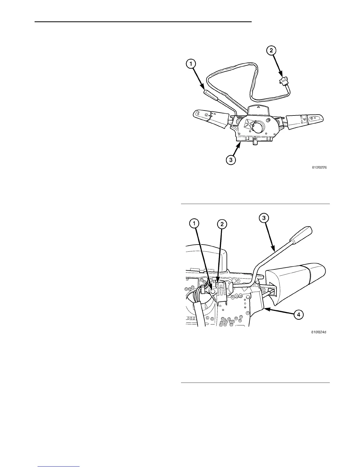
Fig. 3 SPEED CONTROL SWITCH LOCATION
1 - SWITCH HANDLE
2 - PIGTAIL ELECTRICAL CONNECTOR
3 - MULTI-FUNCTION SWITCH
Fig. 4 SPEED CONTROL SWITCH REMOVAL /
INSTALLATION
1 - SWITCH MOUNTING SCREW (1)
2 - SPEED CONTROL SWITCH
3 - SWITCH HANDLE
4 - MULTI-FUNCTION SWITCH
VA SPEED CONTROL 8P - 3

 Loading...


