Page 5 of 12
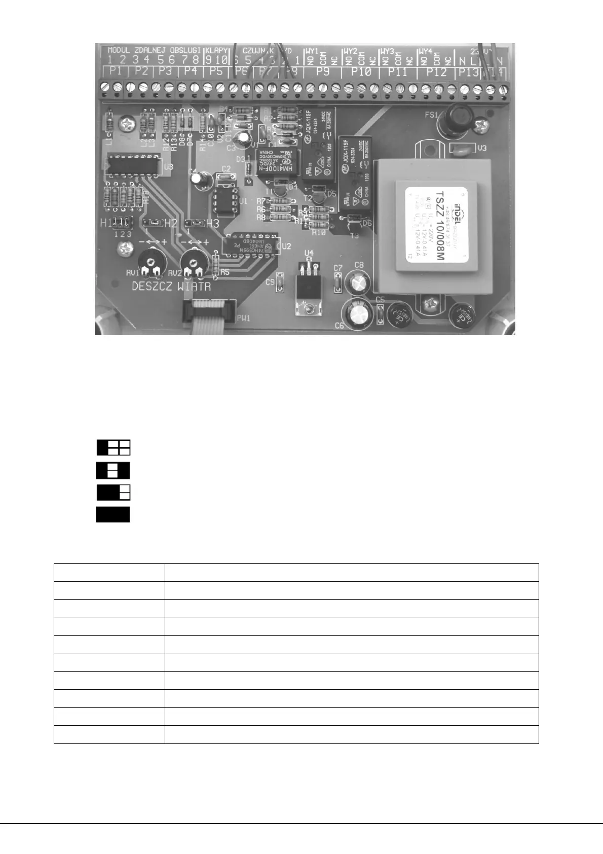
Fig. 2. View of the unit’s interior.
At the left edge of the board, there’s a set of time coding jumpers
H1 (5) used to code the desired time during which the alarm will remain
on after the cause of the alarm (i.e. wind or rain) has ceased:
Minimum alarm duration
4 minutes
6 minutes
8 minutes
10 minutes
Along the top edge of the module's PCB there are terminal strips
(6) which are used to connect the elements of the system:
Description Function
P1 … P4 input for remote control module
P5 input for vent opening sensor
P6 … P7 input for wind/rain sensor
P9 output 1 from the unit (switch)
P10 output 2 from the unit (switch)
P11 output 3 from the unit (switch)
P12 output 4 from the unit (switch)
P13 auxiliary output 230 V, 50 Hz, max 5 A
P14 power supply input 230 V, 50 Hz
On the board there is an circuit breaker FS1 (7) - 125 mA quick.
PW1 contact (8) is used to connect the indicator board mounted in
the unit’s cover.
 Loading...