Do you have a question about the Mercury Security EP1501 and is the answer not in the manual?
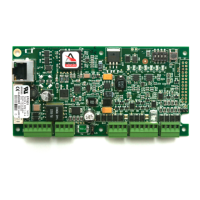
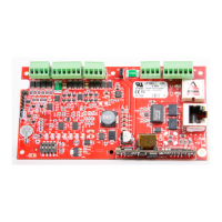
Host communication is via the on-board 10-BaseT/100Base-TX Ethernet port.
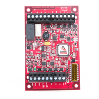
Reader port 1 supports TTL, F/2F, RS-485, tri-state LED, buzzer, and multi-drop devices.
Reader port 2 supports TTL, F/2F, tri-state LED, buzzer, two Form-C relays, and two inputs.
Connection point for the tamper switch.
Jumper to select power source: PoE or 12Vdc.
Button for resetting the device.
Switches for configuring operating modes.
Indicator lights for device status.
Port for network connectivity.
Detailed terminal block connections for inputs, outputs, and power.
Jumpers for various functions like power and Ethernet.
Configures the EP1501 for normal operation with default settings.
Enables default login credentials for initial setup.
Details the default network and communication settings.
Procedure to erase configuration and reset the EP1501 to factory defaults.
Explains powering the EP1501 via PoE or a local 12Vdc supply.
Details the Ethernet interface for host communication.
Details supported reader types (TTL, F/2F, RS-485) and power limits.
Supports multiple RS-485 devices with cable length limits.
Illustrates wiring for D1/D0 readers on both ports.
Illustrates wiring for F/2F readers on both ports.
Lists example remote serial I/O modules compatible with Reader Port 1.
Details OSDP device addressing and baud rate settings.
Describes unsupervised and supervised input configurations.
Explains the use of 1k ohm resistors for supervised circuits.
Details wiring for unsupervised normally closed and normally open inputs.
Explains the use of Form-C relays for locks or alarms.
Recommends using diodes or MOVs to protect relays from EMF feedback.
Details the 12Vdc auxiliary power output and its limitations.
Describes the rechargeable battery backing up SRAM data.
Describes LED sequencing during device initialization.
Defines the meaning of each LED during normal operation.
Indicates Ethernet speed and link status.
Recommends secure password creation and DIP switch settings.
Suggests disabling SNMP, Zeroconf, and enabling data encryption.
Specifies power requirements and output capabilities.
Details Ethernet communication and reader interface specifications.
Lists cable requirements and environmental operating conditions.
Provides dimensions and weight of the unit.
Lists sources for optional mounting accessories like covers and switches.
Diagram showing dimensions and mounting hole patterns for the mounting plate.
Details the one-year limited warranty for defects in material and workmanship.
States the product is not for life-critical applications and limits liability.
| Brand | Mercury Security |
|---|---|
| Model | EP1501 |
| Category | Controller |
| Language | English |