EasyManua.ls Logo

Mercury Security MR50 - User Manual

Mercury Security MR50
5 pages
Print Icon
To Next Page IconTo Next Page
Loading...
Mercury Security Corporation © 2014 MR50 DOC 10107-0009 REV 2.03 Page 1
www.mercury-security.com
2355 MIRA MAR AVE. LONG BEACH, CA 90815-1755, (562)986-9105 FAX (562) 986-9205
This device complies with part 15 of the FCC Rules.
Operation is subject to the following two conditions: (1) This
device may not cause harmful interference, and (2) this
device must accept any interference received, including
interference that may cause undesired operation.
MR50 READER INTERFACE
Installation and Specifications:
1. General:
The MR50 reader interface provides a solution to the OEM system integrator for interfacing to a
TTL/Wiegand/RS-485 type reader and door hardware. The MR50 can accept data from a reader with
clock/data, Wiegand signaling or 2-wire RS-485, also provides a tri-stated LED control and buzzer
control. Two Form-C contact relay outputs may be used for strike control or alarm signaling. Two
inputs are provided for monitoring the door contact and exit push button. Communication to the
interface is accomplished via a 2-wire RS-485 interface. The MR50 requires 12 to 24 Vdc for power.
2. Power, Reader and Door Hardware Wiring:
All interconnections to the interface are via quick-disconnect terminal blocks. The MR50 requires
filtered 12 to 24 Vdc±10% for power. The MR50 supports clock/data, Wiegand or 2-wire RS-485
reader interface signaling. Two inputs are typically used for door contact and exit push button
monitoring. End of line resistors are required for line supervision.
Note: The input power is passed through to the reader terminal strip and is available for powering a
reader. Care must be taken to insure that the input voltage is within the voltage range of the reader.
1
2
3
4
5
6
7
8
J2
TB1
GND
J3
J5
TR-
TR+
VO
D0
DAT
GND
D1
LED
CLK
BZR
TB4
J4
B A
U1
J6
TB3
TB2
K2
K1
I1
I1
I2
I2
GND
VIN
C
NC
NO
C
NO
NC
K2K1
2.35 [59.7]
2.75 [69.9]
3.85 [97.8]
4.25 [108]
TAMPER INPUT, NORMALLY CLOSED
STATUS LEDs
0.20 [5.1]
0.20 [5.1]
Ø0.156 [Ø4.0]
4 PLACES
1K,1%
1K,1%
1K,1%
1K,1%
NC
NO
EXIT REQUEST
NORMALLY OPEN
DOOR CONTACT
NORMALLY CLOSED
NORMALLY CLOSED
COMMON
NORMALLY OPEN
NORMALLY OPEN
NORMALLY CLOSED
COMMON
+12 to 24 Vdc INPUT VOLTAGE
INPUT VOLTAGE RETURN
STRIKE RELAY (K1)
GROUND
BUZZER
LED
DATA1/CLOCK/TR+
DATA0/DATA/TR-
READER POWER
RS-485
INTERFACE
READER
TAMPER, NC
TB4
GND
CLK
LED
D1
DAT
D0
VO
TR+
TR-
GND
BZR
TB1
I1
I2
I1
I2
GND
C
VIN
NO
NC
C
NO
NC
K1 K2
TB3
TB2
8
2
1
5
4
3
7
6
J4
J2
J3
AUX. RELAY (K2)
K1
K2
TR-
GROUND
TR+
I2
I1
SIO COMM.
Question and Answer IconNeed help?

Do you have a question about the Mercury Security MR50 and is the answer not in the manual?

Mercury Security MR50 Specifications

General IconGeneral
ModelMR50
CategoryController
Max doors per controller2
Reader Inputs2
Outputs4
Reader Ports2
Power Supply12V DC
HousingMetal
CommunicationRS-485
Operating Temperature0 to 70 °C
DescriptionThe MR50 is an intelligent, single door interface module used to extend the reach of an access control system. It supports one door, controls access using one or two readers, and monitors door status. Designed for easy installation and use, the MR50 provides a cost-effective way to expand the capacity of an access control system.

Summary

MR50 Reader Interface General Information

MR50 Overview and Capabilities

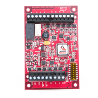
Explains the MR50 reader interface function, connectivity, and power requirements.

Power, Reader, and Door Hardware Wiring

Details on powering the unit, reader, and door hardware connections.

Wiring Details and Protection

Reader Wiring

Wiring diagrams and specifications for connecting readers.

Door Strike Relay Wiring

Wiring for door strike control using Form-C relays, including protection circuits.

Diode Selection for Door Strikes

Recommends diode ratings for protecting door strike circuits.

MOV Selection for Door Strikes

Recommends MOV clamp voltage for AC strike protection.

Communication Configuration

Communication to a Controller

Details on RS-485 communication between MR50 and controller.

Address, Baud Rate, and Encryption Jumpers

Configuration of device address, baud rate, and encryption via jumpers.

Status LEDs and Specifications

Status LED Indicators

Describes the meaning and behavior of the A and B status LEDs.

Technical Specifications

Lists electrical, communication, and mechanical specifications for the MR50.

Environmental, Warranty, and Liability

Operating Environment

Specifies temperature and humidity ranges for operation and storage.

Product Warranty

Details the one-year limited warranty for material and workmanship defects.

Usage Liability

States limitations on product use and Mercury Security's liability.

Related product manuals