Mercury Security Corporation © 2009 MR16in DOC 10107-0010 REV 2.01 Page 3
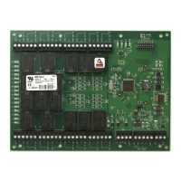
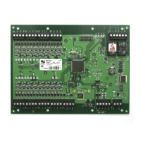
5. Relay Outputs:
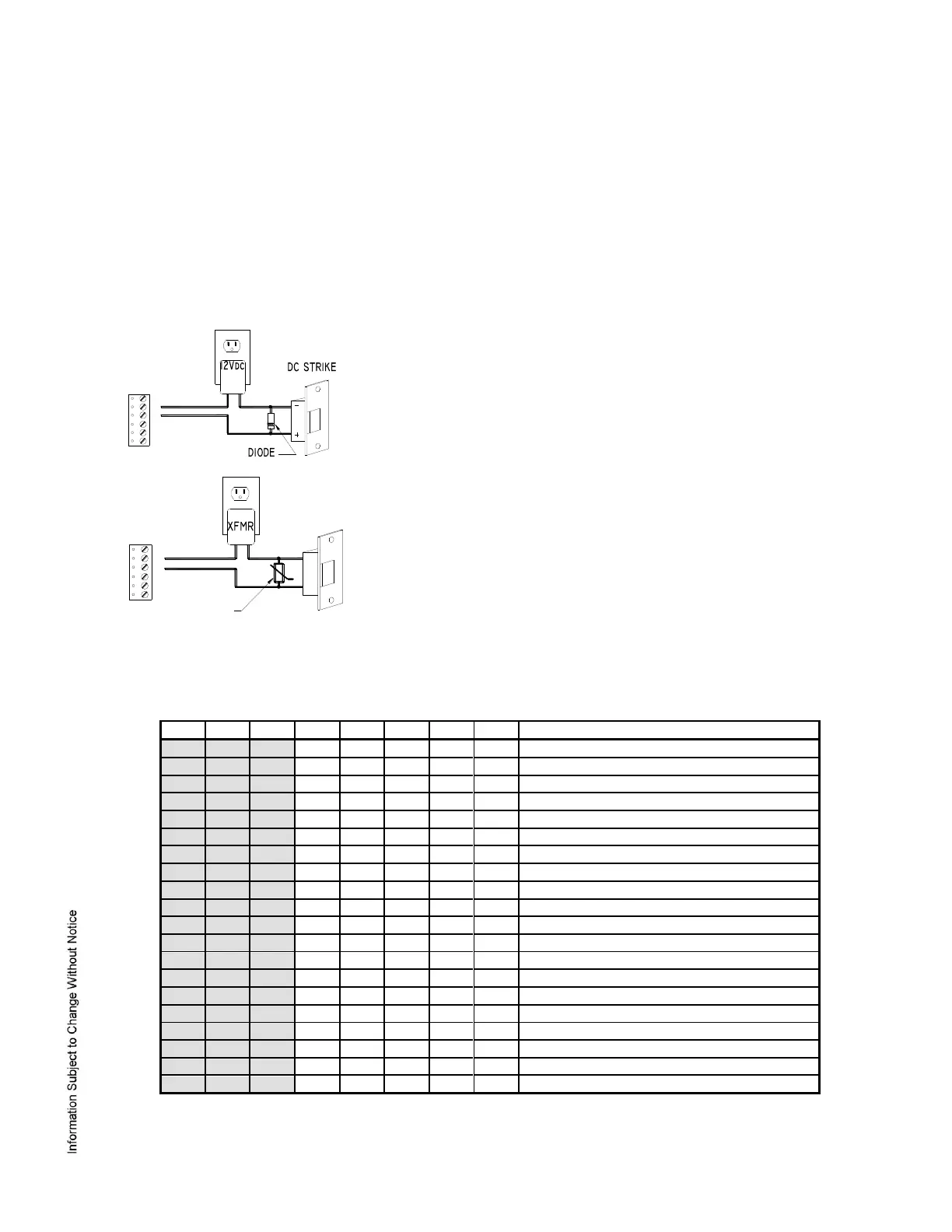
Two form-C contact relays are provided for controlling door strikes or other devices. Load switching can
cause abnormal contact wear and premature contact failure. Switching of inductive loads (strike) also
causes EMI (electromagnetic interference) which may interfere with normal operation of other equipment.
To minimize premature contact failure and to increase system reliability, contact protection circuit must be
used. The following two circuits are recommended. Locate the protection circuit as close to the load as
possible (within 12 inches [30cm]), as the effectiveness of the circuit will decrease if it is located further
away.
Use sufficiently large gauge of wires for the load current as to avoid volt
DIODE SELECTION:
DIODE CURRENT RATING > 1 X STRIKE CURRENT
DIODE BREAK DOWN VOLTAGE: 4X STRIKE VOLTAGE
FOR 12Vdc or 24Vdc STRIKE, DIODE 1N4002 (100V /1A) TYPICAL
MOV SELECTION:
CLAMP VOLTAGE > 1.5 X Vac RMS
FOR 24Vac STRIKE, PANASONIC ERZ-C07DK470 TYPICAL
6. DIP Switch Jumper and Usage:
Switches 1 to 5 select the device address. Switch 6 and 7 select the communication baud rate. Switch 8
enables encrypted communication. All other configuration settings are set via host software.
Continued on next page.
 Loading...