Mercury Security Corporation © 2011 MR52 DOC 10107-0015 REV 2.02 Page 3
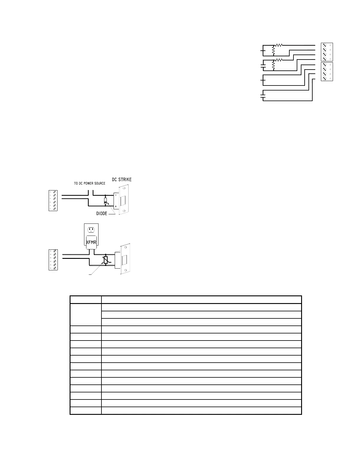
NC
NO
NO
NC
1K,1%
1K,1%
1K,1%
1K,1%
IN1 IN2 IN3 IN4
5. Alarm Contract Wiring:
Inputs 1 to 8 may be configured to use or not to use End-Of-Line (EOL)
resistors, and for normally open or normally closed contacts. Input TMP
is used for monitoring cabinet tamper and PFL input is used power
failure monitoring. These two inputs are for contact closure monitoring
only. They do not use EOL resistor(s). Input configuration is set via host
software.
6. Control Output Wiring:
Six form-C contact relays are provided for controlling door strikes or other devices. Load switching can
cause abnormal contact wear and premature contact failure. Switching of inductive loads (strike) also
causes EMI (electromagnetic interference) which may interfere with normal operation of other equipment.
To minimize premature contact failure and to increase system reliability, contact protection circuit must be
used. The following two circuits are recommended. Locate the protection circuit as close to the load as
possible (within 12 inches [30cm]), as the effectiveness of the circuit will decrease if it is located further
away.
Use sufficiently large gauge of wires for the load current as to avoid voltage loss.
DIODE SELECTION:
DIODE CURRENT RATING > 1 X STRIKE CURRENT
DIODE BREAK DOWN VOLTAGE: 4X STRIKE VOLTAGE
FOR 12Vdc or 24Vdc STRIKE, DIODE 1N4002 (100V /1A) TYPICAL
MOV SELECTION:
CLAMP VOLTAGE > 1.5 X Vac RMS
FOR 24Vac STRIKE, PANASONIC ERZ-C07DK470 TYPICAL
7. Jumper and DIP Switch Usage:
12V = 12Vdc at reader ports. *** See note below ***
PT = VIN “Passed Through" to reader ports
2-Wire/4-Wire Select, install in 2W position only
RS-485 Termination, install in first and last units only
NOTE: The input power (VIN) must be 20Vdc minimum if the 12Vdc selection is to be used.