CDS G3 INTERFACE KIT
Page 6 / 8 © 2016 Mercury Marine 90-8M0114146 eng FEBRUARY 2016
IMPORTANT: Ensure that the correct termination resistor is installed on the CAN P bus. The CAN P bus must be
properly terminated for the tool to communicate reliably. Improper termination will result in communication errors or
complete loss of communication.
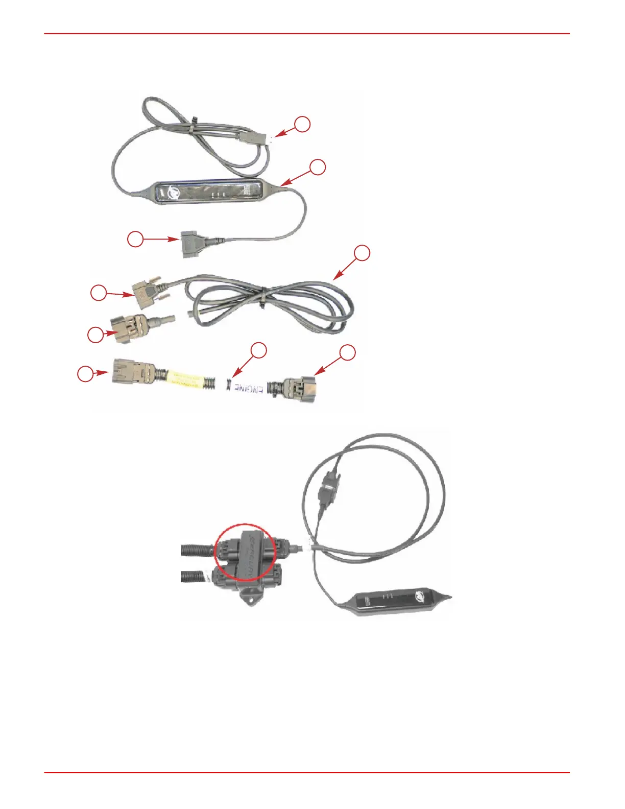
a - SmartCraft interface cable
b - CAN P and H adapter
c - Harness adapter with resistor
d - Connect to engine or J‑box connection
e - Connect to key f of CAN P and H adapter
f - Connects to e
g - Connects to h
h - Connects to g
i - Connects to computer USB port
Junction box connection
Vessels without a Junction Box
1. Insert the SmartCraft Diagnostic Interface USB connector into a powered USB port.
2. Connect the SmartCraft Diagnostic Interface DB9 connector to the CAN P/CAN H adapter harness DB9 connector.
3. Remove the CAN P termination resistor from the engine harness.
IMPORTANT: Ensure that the correct termination resistor is installed on the CAN P bus. The CAN P bus must be
properly terminated for the tool to communicate reliably. Improper termination will result in communication errors or
complete loss of communication.
 Loading...