Epiphone Valve Jr.•Mercury Upgrade Kit 9
ThisprojectanditsdocumentationistheresultoftechnicalinvestigationsmadebytheengineeringstaffofMercury Magnetics.Thedisclosureoftheinformationhereinmaypertaintoproprietaryrightsand
thefurnishingofthesedocumentsdoesnotconstituteanexpresedorimpliedlicensetousesuchmaterials.
Recommended tools for this project:
• SetofPhillipsscrewdrivers
• Wirestrippers
• Goodqualitysolderiron(capableoftempsat>800ºF)
• Electronicsgradesolder
• Soldersuckerand/orwick
• Dremel Toolwithpolishingandcarbidecuttingtips*
• ExactoknifeforcuttingandscrapingPCBtraces*
• Smallneedle-noseplyers
• Smallratchetset(AmericanandMetric)
Synopsis of Upgrade Sequence:
1. Disconnectchassisfromampanddischargethecaps.
2. Removeoldtransformers.
3. DisconnectMainandOutputPCBsandremove/
desoldercomponentsthatwillbechanged.
4. Drillnewtransformersandchokemountingholes.If
you’llbeaddingAlan’s6V6option,drillthesocketand
mountingscrewholesforthat.
5. Mounttransformersandchoke.Install6V6socketand
stand-offconnectorbracketifyouareaddingAlan’s
6V6option.
6. Drillholesforlamentwiresandenlargeholesfor
otherconnectionsintothemainPCB.
7. CuttracesonthemainPCB.
8. SolderbusswirejumperstothemainPCB.
9. Solderinupgrade’sresistorsandcapacitorsontothe
mainPCB.
10.MakeandsolderinlamentsupplyleadsbetweenV1
andV2(EL84and12AX7)sockets.
• Sharpknifeforscrapinginsulationlayerfromtraces
• Electricdrillwith1/16”and11/64”bits
• 1”and9/16”Varibitorsteppeddrillbit
• Silicongoo
• Loctite 290(green)
• PureisopropylalcoholandQ-tips
• Variacandcurrentmeter
*Dremel ToolcanbeusedtocuttracesanddrillholesinPCB.
11.Forthe6V6option,install8-pinsocket’scomponents
andconnectingleads.
12.SolderOT’sleadstotheoutput’sminiPCBand
reconnecttothechassis.
13.Completeconnectionstothe6V6option.
14.SolderremainingleadsforthePT,chokeandtheOT
tothemainPCBandtheOn/Offswitch.
15.ReattachmainPCBtochassis.
16.Usingthesupplieddiagrams,triple-checkyourwork
toensurethatallconnectionsaremadeandare
correct.
17.Powerupusingavariacandampmeter.
CAUTION: DO NOT POWER UP THE AMP
WITHOUT THE SPEAKER CONNECTED!!!!
18.ArrangeleadstominimizeRFandnoise.
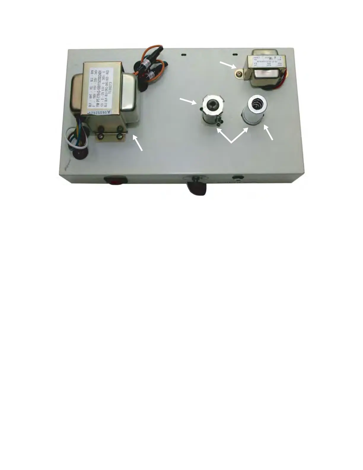
Reference photo of a stock Version 2 or 3 Valve Jr. chassis. Photo shows external chassis layout of
transformers and tubes. Note that hte EL84 and 12AX7 tube (or valve) sockets are identical. Be care-
ful NOT to accidentally switch these tubes!
Original Power Transformer
Generic EL84
Power Tube
Tube Retainers
Original Output
Transformer
Generic 12AX7
Preamp Tube

 Loading...